Ardumower PCB ru
Inhaltsverzeichnis
- 1 Описание
- 2 Needed modules
- 3 PCB
- 4 PCB versions
- 5 Перемычки на печатной плате (джамперы)
- 6 Модули для печатной платы
- 7 Разъемы на печатной плате
- 8 Power supply
- 9 Download and flash Arduino code
- 10 First-time calibration
- 11 Diagnostics/troubleshooting
- 12 Starting the mower
- 13 Error counter / error beeps
- 14 Settings
- 15 Further links
Описание
В этом разделе описывается, как собрать печатную плату Ardumower, прошить Arduino и настроить газонокосилку-робота. Плата построена вокруг готовой Arduino Мега 2560 (54 порта ввода/вывода).
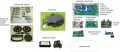
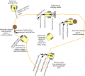
Components overview
Chassis components
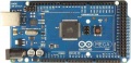
Ardumower's heart: Arduino Mega 2560 microcontroller
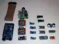
Modules available in the shop
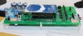
Ardumower PCB connects all modules (available in the shop)
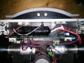
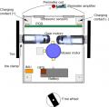
Chassis and PCB inside
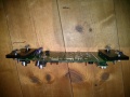
PCB mount


Needed modules
All modules can be purchased as complete kits via the shop ![]() .
.
- Main functions
- Arduino cable (female-female and male-female jumper cable)
- Arduino Mega 2560 (or Arduino Due)
- Adjustable DC voltage step-down modules (3.3v, 5v, 8v)
- dual motor driver module with integrated current sensor (2 wheel motors)
- current sensor module
- motor driver module with integrated current sensor (mower motor)
- Resistors, Capacitors, Fuse
- Piezo buzzer, button, ON/OFF switch
- Perimeter sender (optional)
- Arduino Nano
- DC voltage step-down module
- motor driver module with integrated current sensor
- Perimeter receiver (optional)
- pre-amplifier module
- Capacitor, Receiver coil
- Additional modules
- IMU module (gyro, accel. compass) (REQUIRED)
- realtime clock module (REQUIRED)
- Bluetooth module (for phone control, RECOMMENDED)
- ultrasonic sensor module (optional)
PCB
The printed circuit board (PCB) connects all electronic modules. The PCB is made with the following design parameters:
- PCB dimensions 241x114mm
- All modules (motor driver, Bluetooth, etc.) can be soldered (or plugged) on the PCB (modules are available in the Ardumower shop)
- Uses the Arduino Mega 2560
- Optional: can use Arduino Due via additional adapter PCB
- Optional: integrated charging circuit (current limiting)
- All connections are available on connectors as well as +5V and GND
- Max. trace current (for motors): 8A
PCB versions
Robot PCB v0.5 (initial prototype)
Robot PCB v1.2 (minor layout changes)
- Schematics
- Photos
- Build instructions
- Build instructions (English translation)
- WorkaRound20150527
- WorkaRound20150530
- Motor-decrease noise REV20150531, (English comments)
- Protector board
Robot PCB v1.3 (in development)
- simplified design (Due adapter will be externally)
- motor driver protection
- battery-off circuit, safety-button
- sets 'reference-design' and required modules: 3x DC/DC, RTC, IMU
NOTE: The schematics and PCB files were created with KiCad. They can be downloaded from github and can be edited by open source KiCAD software (Download here or here).
Перемычки на печатной плате (джамперы)
Внимание! Я как переводчик так и не понял смысл первых трех функций и перевел их "дословно". Необходимо уточнение и более подробное описание.
| Функция | Функция используется | Функция НЕ используется | Комментарий |
|---|---|---|---|
| Встроенная схема контроля зарядки через регулируемый регулятор напряжения (LM350T) с потенциометром для регулировки зарядного напряжения
(Рекомендуется не использовать --Unlogic (Diskussion) 20:12, 22. Aug. 2015 (CEST) Что за бред???) |
D7: Диод установлен
D3: Диод установлен C1, C4, U4, RV1: используется |
D7: не используется, замкнуть выводы
D3: не используется, замкнуть выводы C1, C4, U4, RV1: не используется |
Не используйте, если зарядка осуществляется через отдельное внешнее зарядное устройство |
| Внешнее питание во время зарядки (Рекомендуется не использовать) | JP6: Перемычка установлена
JP7: Перемычка не установлена D4: Диод установлен C5: не используется |
JP6: Перемычка не установлена
JP7: Перемычка установлена D4: не используется, замкнуть выводы C5: используется |
Используется для питания платы от внешнего источника во время зарядки (когда аккумулятор отсоединятся от платы для зарядки) |
| Arduino контролирует реле зарядки (рекомендация использовать) | JP4: Перемычка установлена
JP5: Перемычка не установлена |
JP4: Перемычка не установлена
JP5: Перемычка установлена |
Используется для того, чтобы Arduino контролировала реле зарядки (не автоматическая зарядка) |
| Arduino Due (3.3V ввод-вывод) | LP0, ..., LP15: Перемычка не установлена | LP0, ..., LP15: Перемычка установлена | Не используйте, если у вас Arduino Mega (проверьте схему, на ней есть дорожки между этими разъемами!!!) |
| Питание Bluetooth-модуля = 3.3V | JP8: Перемычка не установлена
JP9: Перемычка установлена |
JP8: Перемычка установлена
JP9: Перемычка не установлена |
Большинство последних модулей используют 3.3V |
| Режим программирования Bluetooth-модуля | JP2: Перемычка установлена | JP2: Перемычка не установлена | Используется для перепрограммирования символьной скорости, имени, пин-кода для подключения. |
Модули для печатной платы
| Модуль | Назначение | Устройство | Выводы | Обязательно | Комментарий |
|---|---|---|---|---|---|
| U1 | DC/DC-конвертер (10V) | LM2596 | GND, Vout, Vin, GND | Да | |
| U2 | Bluetooth-модуль | HC-05 | VCC, GND, TXD, RXD, Key, LED | Нет | |
| U3 | Датчик тока зарядки | INA169 | VCC, GND, OUT, IP+, IP-5 | Нет | |
| U4 | Контроль зарядки | LM350T | AJD, OUT, IN | Нет | |
| U5 | Датчик тока зарядки | INA169 | VCC, GND, OUT, IP+, IP-5 | Нет | |
| U6 | DC/DC-конвертер (3.3V) | LM2596 | GND, Vout, Vin, GND | Да | |
| U7 | DC/DC-конвертер (5V) | LM2596 | GND, Vout, Vin, GND | Да | |
| U8 | Часы реального времени | DS1307 | Batt, GND, VCC, SDA, SCL, DS, SQ | Нет | |
| U9 | Wifi | ESP8266 | TX, CH_PD, Reset, VCC, GND, GP_IO2, GP_IO0, RX | Нет | |
| U10 | Преобразователь питания 5V->3V (для Arduino Due) | Нет | |||
| U11 | Wifi | ESP8266 | TX, CH_PD, Reset, VCC, GND, GP_IO2, GP_IO0, RX | Нет | Альтернативное место подключения U9 |
Разъемы на печатной плате
| Разъем | Feature | Выводы | Обязательно | Комментарий |
|---|---|---|---|---|
| P1 | Sonar center (HC SR-04) | 5V, GND, Trigger, Echo | Нет | |
| P2 | Sonar right (HC SR-04) | 5V, GND, Trigger, Echo | Нет | |
| P3 | Sonar left (HC SR-04) | 5V, GND, Trigger, Echo | Нет | |
| P4 | резервный | Нет | ||
| P5 | IMU (gyro,acceleration,compass) (GY-80) | Нет | ||
| P6 | Lawn sensor | Нет | ||
| P7 | Status LEDs | Нет | ||
| P8 | Odometry right | Нет | ||
| P9 | Odometry left | Нет | ||
| P10 | GPS (GY-NEO6MV2) | Нет | ||
| P11 | Bumper | GND, GND, right, left | Нет | |
| P12 | Perimeter coil (center or left) | 5V, GND, perimeter | Нет | |
| P13 | R/C remote control | 5V, GND, mow, steer, speed, switch | Нет | |
| P14 | Measurement points | 5V, GND, (Depending on JP15: 3.3V, 5V or Arduino 3.3V) | Нет | |
| P15 | Wheel motor left | M1OUT1, M1OUT2 | Да | |
| P16 | Optional motor driver input | Нет | Не подключайте | |
| P17 | Optional motor driver input | Нет | Не подключайте | |
| P18 | Wheel motor right | M2OUT1, M2OUT2 | Да | |
| P19 | Tilt sensor | 5V, GND, tilt | Нет | |
| P20 | Button (Start/Stop) | Да | ||
| P21 | Drop sensor right | Нет | ||
| P22 | резервный | Нет | ||
| P23 | резервный | Нет | ||
| P24 | резервный | Нет | ||
| P25 | резервный | Нет | ||
| P26 | резервный | Нет | ||
| P27 | резервный | Нет | ||
| P28 | резервный | Нет | ||
| P29 | резервный | Нет | ||
| P30 | Perimeter coil right | Нет | ||
| P31 | Drop sensor left | Нет | ||
| P32 | GND | Нет | ||
| P33 | 5V | Нет | ||
| P34 | 3.3V | Нет | ||
| P35 | Mower motor RPM | Нет | ||
| P36 | резервный | Нет | ||
| P37 | Mower motor | Да | ||
| P38 | резервный | Нет | ||
| P39 | резервный | Нет | ||
| P40 | User switches | Yes | ||
| P41 | Датчик дождя | Нет | ||
| P42 | Charging pins | Нет | ||
| P43 | Battery (24V) | Да | ||
| P44 | Wifi-модуль (ESP8266) | Нет | ||
| P45 | резервный | Нет | ||
| P46 | резервный | Нет |
Power supply
Please also read the section 'Voltages' under Motor driver for more information on motor voltages.
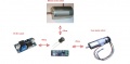
It is recommended to use a voltage step-down converter (e.g. module using LM2596) to generate the 5V voltage for the Arduino and all additional modules. Before connecting, set the voltage of the converter to 5V.
![]() Warning : never connect more than 5V on the Arduino 5V pins, or you will damage the Arduino. Therefore, always measure the 5V voltage before connecting it to the Arduino 5V pin!
All components together (as shown in the schematics) need about 5W power.
Warning : never connect more than 5V on the Arduino 5V pins, or you will damage the Arduino. Therefore, always measure the 5V voltage before connecting it to the Arduino 5V pin!
All components together (as shown in the schematics) need about 5W power.
NOTE: Keep away coil/pre-amplifier from DC/DC converters!

Download and flash Arduino code
NOTE: If you have never worked with Arduino before, read our 'Arduino first steps' introduction.
You have two options:
- Download github code (recommended) OR
- Download v0.9.3 code (old, not recommended)
Finally, download and start the Arduino IDE to flash the code to your Arduino.
Arduino Version: It is very Importent that you use the Arduino IDE version 1.6.3 or above AND select the right Board (Mega 2560 or Due).
![]() Note: Always verify that the pin configuration in your Arduino code (config.h/mower.cpp) matches your actual circuit!
Note: Always verify that the pin configuration in your Arduino code (config.h/mower.cpp) matches your actual circuit!
First-time calibration
Wheel motors
![]() Security note: For security reasons, always remove mower blades in your first tests!
Security note: For security reasons, always remove mower blades in your first tests!
Initially, you should verify that the wheel motors are controlled correctly and in the right direction. The software offers a diagnostic mode. Open the serial console in the Arduino IDE (CTRL+SHIFT+M) and set the baudrate to 19200. The motor and sensor values should appear constantly:
    20 OFF  spd    0    0    0 sen    0    0    0 bum    0    0 son...
    21 OFF  spd    0    0    0 sen    0    0    0 bum    0    0 son...
    22 OFF  spd    0    0    0 sen    0    0    0 bum    0    0 son...
    23 OFF  spd    0    0    0 sen    0    0    0 bum    0    0 son...
    24 OFF  spd    0    0    0 sen    0    0    0 bum    0    0 son...
    ...
Now, press the key ‘t’ on the keyboard, and confirm using ENTER. The diagnostic mode should appear, and you can test your motors.
ADC calibration
Run the ADC calibration once (either via serial console with command 'd' or "pfodApp->ADC Calibration"), so that the received signal is symmetric around zero.
Diagnostics/troubleshooting
Each time a sensor triggers, its corresponding sensor counter increases. The sensor trigger counters as well as the current sensor values can be viewed on the serial console. The following values are shown for the trigger counters in the serial console:
- Time of state machine's state (ms)
- loop()-counts per second
- choosen Verbose-Mode (0=counter readings/1=current values/2=current values)
- current state machine state (FORW, REV, ROLL etc.)
- drive home? (1/0)
- "spd" - Control/speed motors: left (PWM), right (PWM), mower (RPM)
- "sen" - Current limit exceeded counter motors: left, right, mower
- "bum" - bumper counter: left, right
- "son" - Ultrasonic-distance threshold exceeded (counter)
- "pit/roll" - Tilt (computed by acceleration sensor)
- "com" - compass course
- "per" - Perimeter loop detected: counter
- "bat" - Battery voltage
- "chg" - Charging current
Using the key 'v', you can toggle between sensor trigger counters and current sensor values.
![]() Additionally, you can use pfodApp (Android) to plot the sensors (trigger counters and current values) over time. This allows you to wirelessly monitor your robot mower for error diagnostics. It is highly recommended.
Additionally, you can use pfodApp (Android) to plot the sensors (trigger counters and current values) over time. This allows you to wirelessly monitor your robot mower for error diagnostics. It is highly recommended.
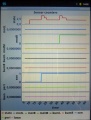
Sensor trigger counters
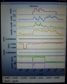
Sensor measurement values


Starting the mower
To start the mower, you need to add a button and a buzzer:
pinButton —o Button o— GND (button for ON/OFF)
pinBuzzer —o Buzzer o— GND (Piezo buzzer)
Now, press the button as long as you hear the beeps:
Mode (press button for x beeps):
1 beeps : Normal mowing (using blade modulation if available)
2 beeps : Normal mowing (without blade modulation)
3 beeps : Drive by model remote control (RC)
4 beeps : Drive without mowing
5 beeps : Find perimeter and track it
Error counter / error beeps
If there's a communication problem or another serious problem, the error counter increases. The error counter can be monitored via pfodApp. Additionally, the robot mower will beep when started.
See section Troubleshooting for details on all errors.
I2C bus / error beeps
Several components (Arduino Nano, RTC, IMU, etc.) are communicating via the I2C bus (SDA/SCL wires). These wires should be very short (maybe even twisted) and they should be far away from DC converter and motor drivers. If there's a communication problem, the error counter will increase and robot will beep when started. The error counter can be monitored via pfodApp.
Settings
The robot uses settings that you can adjust for your own robot and environment (via pfodApp or directly in the code). The default settings (factory settings) are stored in the config file 'mower.cpp'.
The settings can be adjusted via Android phone (pfodApp).
General settings
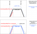
Motor speed settings
General config file idea


Important: If you uploaded a new version into your robot, reset all settings via pfodApp once (Settings->Factory reset). This will delete all existing settings. Old settings can produce malfunction if the internal settings format has changed.