Hauptseite: Unterschied zwischen den Versionen
Aus www.wiki.ardumower.de
(→Building, Downloading, Running (steps)) |
(→Required parts: Ardumower) |
||
| Zeile 16: | Zeile 16: | ||
*Important modules to choose: | *Important modules to choose: | ||
**Accessories Set (resistors, pin strips etc.) | **Accessories Set (resistors, pin strips etc.) | ||
| − | ** | + | **[https://www.marotronics.de/Protector-Board-zum-Schutz-der-Motortreiber-vor-hohen-Induktionsspannungen 2 x Motor driver protection PCB] |
**1 x Mega Board 2560 R3 | **1 x Mega Board 2560 R3 | ||
**1 x INA169 Current Sensor Board | **1 x INA169 Current Sensor Board | ||
**2 x Dual motor driver MC33926 | **2 x Dual motor driver MC33926 | ||
| − | **3 x DC-DC LM2596 Step-Down Converter | + | **[https://www.marotronics.de/DC-DC-Spannungsregler-LM2596-Step-Down-Regler-einstellbar 3 x DC-DC LM2596 Step-Down Converter] |
**1 x Wireless Bluetooth module HC-05 | **1 x Wireless Bluetooth module HC-05 | ||
**1 x Real Time Clock I2C DS1307 | **1 x Real Time Clock I2C DS1307 | ||
| − | **1 x 24 Volt Charger for the Ardumower LithiumIon Battery | + | **[https://www.marotronics.de/Ladegeraete-fuer-den-Ardumower-Akkus-24V-mit-Status-LED-auch-fuer-Li-Ion-Akkus 1 x 24 Volt Charger for the Ardumower LithiumIon Battery] |
| − | + | ||
*Optional modules: | *Optional modules: | ||
| − | **BumperDuino (intelligent bumper sensor) | + | **[https://www.marotronics.de/Bumper-Duino-Dual-Drucksensor-Board-zB-fuer-Arduino-Raspberry-pi BumperDuino (intelligent bumper sensor)] |
| − | **Perimeter sender and receiver | + | **[https://www.marotronics.de/Perimeter-Sender-Board-Prototyp-mit-Platinen-Zubehoer Perimeter sender] and [https://www.marotronics.de/Schleifenempfaenger-Kit-perimeter-receiver-Kit receiver] |
| − | **Charger Accessories Set (Lead Battery) | + | **[https://www.marotronics.de/Zubehoer-Set-fuer-die-Laderegelung-Blei-Batterien Charger Accessories Set (Lead Battery)] |
| − | **Ultrasonic sensor HC-SR04 (up to 3 supported) | + | **[https://www.marotronics.de/HC-SR04-Ultraschallsensor-Ultrasonic-Ranging-Module Ultrasonic sensor HC-SR04 (up to 3 supported)] |
| − | **Rain sensor | + | **[https://www.marotronics.de/Regensensor-Modul-YL-38-fuer-Arduino-Raspberry-PI-Regentropfen-Sensor-Naessesensor Rain sensor] |
| − | **IMU GY-80 | + | **[https://www.marotronics.de/9-Achsen-IMU-Sensor-GY-801-L3G4200D-ADXL345-HMC5883L-BMP180 IMU GY-80] |
| − | **Undervoltage protection PCB | + | **[https://www.marotronics.de/Unterspannungsschutz-Board-Undervoltage-lockout-board Undervoltage protection PCB] |
| − | **GPS Module GY-GPS6MV2 | + | **[https://www.marotronics.de/NEO-6M-GPS-Modul-GY-GPS6MV2-NEO-6M-Flight-Controller-zb-fuer-Arduino GPS Module GY-GPS6MV2] |
| − | **WIFI/Wlan Module ESP8266 ESP01 | + | **[https://www.marotronics.de/ESP8266-WIFI-Wlan-Serial-Modul-ESP01-fuer-Arduino WIFI/Wlan Module ESP8266 ESP01] |
*1 x [http://www.asn-shop.de/Ardumower-Power-Pack-259V-45Ah Ardumower Power Pack] | *1 x [http://www.asn-shop.de/Ardumower-Power-Pack-259V-45Ah Ardumower Power Pack] | ||
Version vom 31. Mai 2016, 10:37 Uhr
-> Deutsche Version
-> Russian Version (outdated)
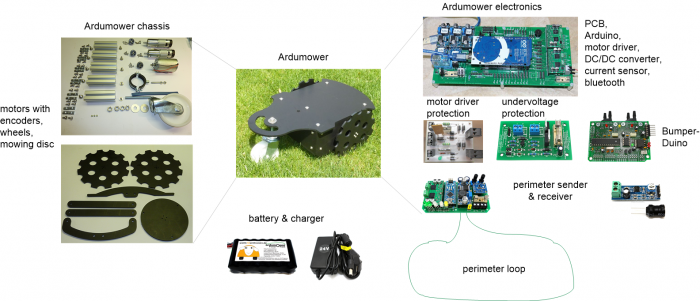
Ardumower WIKI - the manual for your ArdumowerRequired parts: ArdumowerAll modules can be purchased as complete kits via the shop What is needed for building your Ardumower:
Required parts: Perimeter loopA perimeter loop is optional but recommended.
Building, Downloading, Running (steps)Here are the steps for building your DIY Ardumower:
Ardumower Reference
Your robot mower project / Dein Rasenroboter-ProjektDescribe your own robot mower project on a new WIKI page / Beschreibe Dein eigenes Rasenroboter-Projekt auf einer neuen WIKI-Site: Your Ardumower extension / Deine Ardumower ErweiterungDescribe your own robot mower extension or improvement (optical, computer vision, IR landmarks, sound, navigation, wireless, or any other addition) on a new WIKI page / Beschreibe Deine eigene Erweiterung oder Verbesserung des Ardumowers:
Further links |


