Laden: Unterschied zwischen den Versionen
(→Charger) |
(→Ladegerät) |
||
| Zeile 15: | Zeile 15: | ||
* Laden des Akkupacks über dei Ladeanschlüsse des Roboters | * Laden des Akkupacks über dei Ladeanschlüsse des Roboters | ||
| − | * | + | * Einhaltung der maximalen Ladespannung (Ladeschluss-Spannung) |
| − | * | + | * Einhaltung dess maximalen Ladestroms (Ladestrom-Begrenzung) |
| − | + | Wenn du ein vorhandenes Ladegerät benutzt, sind diese Anforderungen mit höchstwahrscheinlich erfüllt. | |
=Total power balance= | =Total power balance= | ||
Version vom 14. Juli 2015, 11:36 Uhr
Inhaltsverzeichnis
Grundprinzip
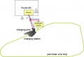
Der Roboter findet seine Ladestation, wo er wieder aufgeladen wird mit Hilfe der Perimeter-Schleife. Er fährt also solange in Uhrzeiger-Richtung an der Schleife entlang bis er eine Ladespannung an den Ladeanschlüssen feststellt. Hier stoppt der Roboter und lädt seinen Akku wieder auf.
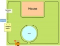
Perimeter-Schleife unter der Ladestation
Komponenten der Ladestation
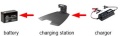
Ladestation
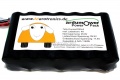
Sony Konion 7S2P Akkupack (29.4V, 4500 mAh)


Ladegerät
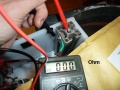
wir benutzen ein Lithium Ion e-bike Ladegerät (29.4V, 1.5A Ladestrom-Begrenzung) das über den Marotronics-Shop shop ![]() bezogen werden kann . Das Ladegerät wird in einem geschützten Bereich untergebracht (z.B. im Haus) und mit der Ladestation verbunden. Das Ladegerät sollte folgendes leisten( hier für Lithium-Ionen-Zellen, bei Bleiakkus ist es ähnlich aber weniger kritisch):
bezogen werden kann . Das Ladegerät wird in einem geschützten Bereich untergebracht (z.B. im Haus) und mit der Ladestation verbunden. Das Ladegerät sollte folgendes leisten( hier für Lithium-Ionen-Zellen, bei Bleiakkus ist es ähnlich aber weniger kritisch):
- Laden des Akkupacks über dei Ladeanschlüsse des Roboters
- Einhaltung der maximalen Ladespannung (Ladeschluss-Spannung)
- Einhaltung dess maximalen Ladestroms (Ladestrom-Begrenzung)
Wenn du ein vorhandenes Ladegerät benutzt, sind diese Anforderungen mit höchstwahrscheinlich erfüllt.
Total power balance
- 2 x Gear motors each 1A (under heavy load): 2A, 27 volt (measured at max. 80% accuracy by motor drivers)
- 1 x Mower motor 1A (under normal load): 1A, 27 volt (measured at max. 80% accuracy by motor drivers)
- PCB: 1A, 5 volt (not measured by PCB)
Total: 3A * 27v + 1A * 5v = 81W + 5W = 86W
Battery
For the battery, we are using a 'Sony Konion 7S2P' Lithium Ion battery pack (Sony Konion US18650V3 2250 mAh cells, Li-Mn), 29.4V x 4500 mAh = 132 Wh, 500 recharge cycles, 126 x 36 x 65 mm (LBH).
Using this battery with the Ardumower motors, the mowing time is about 1.5 hours (132 Wh / 86W).
battery charge/discharge conditions for optimal battery life time:
- charging per cell: max 4.15v (0.3A - 0.1A charging cutt-off)
- discharging per cell: min 3.1v
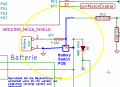
Standby-off / Under-voltage protection
There are two reasons for a battery switch (standby-off mechanism):
Reason1: If the robot was not started within 5 minutes, it should turn battery off to save energy.
Reason2: Modern batteries should not be completely discharged. When the robot isn't able to charge for some reason and when the battery is below a certain threshold, it should be able to switch off the battery itself (undervoltage protection)
Idea:
- User presses existing START/POWER button, that switches on the MOSFET for the time of pressing
- Arduino starts and immediately also switches on MOSFET (via Arduino pinBatterySwitch)
- If undervoltage detected, Arduino switches off MOSFET (via Arduino pinBatterySwitch)
- Emergy button is still used for completely switching ON/OFF power
- POWER/START button: switches-on operation voltage (1st one second press), starts robot in automatic mode (2nd one second press)
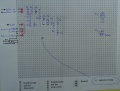
Ardumower complete system motor start current
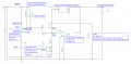
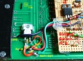
Battery switch-off circuit
Battery switch-off PCB
Ardumower PCB modification circuit
Ardumower PCB modification
Idea for future PCB


BOM:
1x IRF9540N  P-MOSFET   T1   (or IRF5210)
1x BC337 NPN   T2
1x Zener Diode 15V ZD15  Z1
2x Diode 1N4148 D2, D3
2x Diode 1N5819 50V D1, D4
1x 22 uF C1
1x 1k R4
2x 10k (R3, R8)
1x 30k R6
2x 100k  (R2, R7)
Robot charging
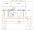
In the robot itself, the battery voltage is monitored (see diagram below). So it can be determined when the robot must go to the charging station. The robot and the voltage and the current during charging is controlled. So it can be determined whether the robot has reached the charger and when the battery is fully charged again.
robot charging circuit:
 Robot charging (+)---+------+-- relais ---- current sensor ----- battery (+)
                             |
                             ---- voltage sensing
 Robot charging (-)-- +------------------------------------------ battery (-)
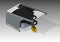
Charging station
Ideally, the charging station also powers the perimeter loop sender.
charging station circuit:
 AC power supply => Charger 24V (+)----- Charging station charger pin(+)
                    GND         (-)----- Charging station charger pin(-)
                    Charger 24V (+)----- DC-DC converter 12V => Perimeter sender MC motor driver
                                                             => Perimeter sender Arduino Nano Vin
Charge monitoring/Battery settings
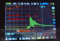
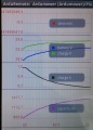
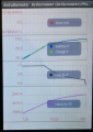
Via pfodApp (Android) you can monitor the charging process.
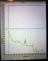
Charging plot
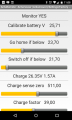
Battery settings
Battery fully charged
Charging with timeout


Charging station ideas


Charging contacts


Videos