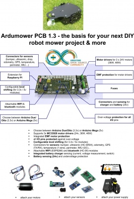
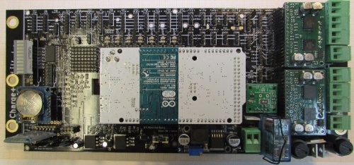
PCB 1.3 (English)
Aus www.wiki.ardumower.de
This page describes how to assemble PCB 1.3, how to add modules and how to configure the PCB.
NOTE: WE ARE CURRENTLY WORKING ON THIS PAGE - PLEASE LOOK AT PCB 1.2 FOR MISSING INFORMATION
Inhaltsverzeichnis
Schematics, Drawings, Photos
Videos
- Assembly part 1 (jumper, capacitors (power), INA, jumper power, bargraph, bluetooth, jumper I2C bus)
- Assembly part 2 (motor drivers)
- Assembly part 3 (Arduino, protection, MOSFET, fuse holder, relay)
- Assembly part 4 (back side: odo-divider, power connectors, buzzer, resistors, capacitors)
- Assembly part 5 (sensor jumpers, connector sockets)
- Assembly part 6 (Capacitors motor output stage )
- Assembly part 7 (Placing into operation)
Checklist
- set jumper JP13 on PCB back side for a Marotronics Arduino Due (for automatic reset)
- set jumper JP12 (GPS signal voltage) to 3.3VP for Marotronics GPS module
- set jumper JP7 (GPS operating voltage) to 5VP for Marotronics GPS module
- set jumper JP10 (Bluetooth signal voltage) to 3.3VP for Marotronics Bluetooth module
- set jumper JP4 (Bluetooth operating voltage) to 5V for Marotronics Bluetooth module
- set jumper JP6 (WIFI operating voltage) to 3.3V for Marotronics WIFI module
- set jumper JP11 (WIFI signal voltage) to auf 3.3V for Marotronics WIFI module
- set jumper JC2 (IMU signal voltage) to 3.3V for Marotronics IMU module
- only set jumpers JC2, JC3, JC4, JC5, JC6, JC7 if there is a corresponding I2C module installed
- press button P20 to power-on PCB
Forum
http://www.ardumower.de/index.php/de/forum/ardumower-pcb/1348-building-instruction-for-the-1-3-board

