How to find defective components: Unterschied zwischen den Versionen
Aus www.wiki.ardumower.de
| Zeile 23: | Zeile 23: | ||
To be continued... | To be continued... | ||
| + | |||
| + | '''Good luck with your measurements!''' | ||
| + | |||
| + | PS: You can find the complete PCB1.3 schematics here: | ||
| + | https://github.com/Ardumower/ardumower/tree/master/Dokumentation/Megashield%20SVN%20V1.3 | ||
Version vom 25. September 2020, 18:05 Uhr
Here are examples on how to find defective components on your PCB1.3.
Problem: Battery does not charge.
Solution:
- Remove charging relay K3.
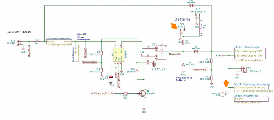
- Connect charger, ensure charger cable (-/GND) is connected to the side marked as '-' at the PCB P42 connector and charger cable (+) is connected to the side marked as '+' at the PCB P42 connector.
- Ensure the yellow station LED near charging relay is going ON.
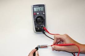
- Using a multimeter (volt/DC) measure voltage directly at charger connector P42 (- and +), ensure charger voltage at P42 is approx. 29V.
- Measure voltage between charger P42 GND and left and right side of the fuse EF1. It should again have approx. 29V.
- Disconnect charger.
- Insert charging relay K3.
- Connect charger again.
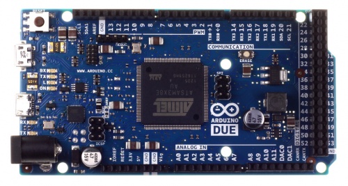
- Measure voltage between P42 GND and Arduino 'pinChargeRelay' (pin 50, see Arduino pinout below). It should have 3.3V which means the Arduino controls the charging relay to go ON.
- Ensure the charging relay is going ON (makes a hearable clicking noise when charger is connected).
To be continued...
Good luck with your measurements!
PS: You can find the complete PCB1.3 schematics here: https://github.com/Ardumower/ardumower/tree/master/Dokumentation/Megashield%20SVN%20V1.3


