Ardumower Sunray
Inhaltsverzeichnis
- 1 NOTE: everything here is still in development! Use Azurit firmware instead if you need a working firmware...
- 2 Significant changes compared to Azurit Firmware
- 3 Requirements
- 4 Bluetooth BLE module
- 5 PCB1.3 GPS pin fix
- 6 RTK base
- 7 RTK rover
- 8 Rover configuration
- 9 Firmware
- 10 Phone App
- 11 Troubleshooting
- 12 Discussion / forum thread
NOTE: everything here is still in development! Use Azurit firmware instead if you need a working firmware...
Ardumower Sunray is an alternative Firmware (experimental) for the Ardumower. It requires PCB1.3, Arduino Due, ArduSimpleRTK kit and a phone (Android/iOS). It uses RTK to localize itself without a perimeter wire.
Demo video: coming soon
Significant changes compared to Azurit Firmware
- Optimized for PCB 1.3
- Optimized for Arduino Due
- Optimized for RTK
Requirements
- Ardumower motors using odometry
- Ardumower PCB 1.3 (incl. MC33926 motor drivers)
- Arduino Due
- SimpleRTK2B - starter kit LR IP67
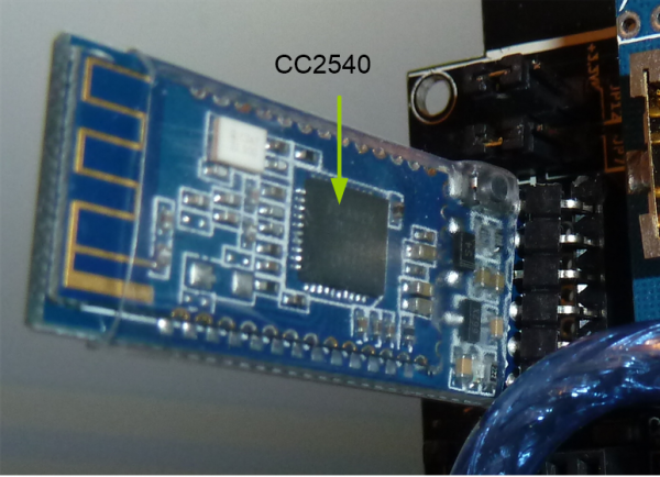
- Bluetooth BLE module (CC2540) and a smartphone (Android/iOS)
Bluetooth BLE module
1. Install Bluetooth 4.0/BLE module on your Ardumower PCB1.3 (replace any installed Bluetooth 2.0 module).
IMPORTANT: Verify the pinout of your BLE module is matching your PCB pinout (shown at the PCB1.3 back side)!
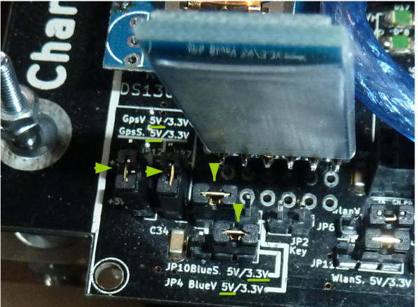
2. Set JP10 (Bluetooth signal level) to 3.3V
3. Set JP4 (Bluetooth voltage) to 5V
4. Set JP12 (GPS voltage) to 5V
5. Set JP7 (GPS signal level) to 5V
PCB1.3 GPS pin fix
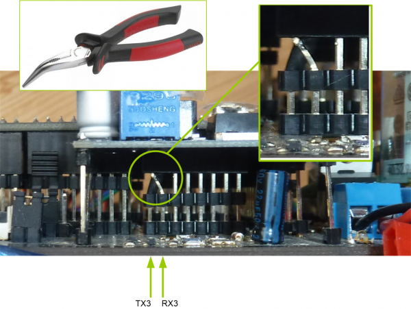
The pins TX3 and RX3 are incorrectly routed on PCB1.3 - Fix it by swapping the TX3 and RX3 pin headers as shown eblow:
RTK base
- Make sure you have the simpleRTK2B marked as 'BASE' in your hands (look at simpleRTK2B PCB label at backside!)
- Connect Xbee LongRange antenna
- Connect GPS multifrequency antenna
- Connect USB 5v to power the base module
- Your base antenna should have clear view to the sky in all directions without any obstacles. For best results install GPS antenna on the roof.
RTK rover
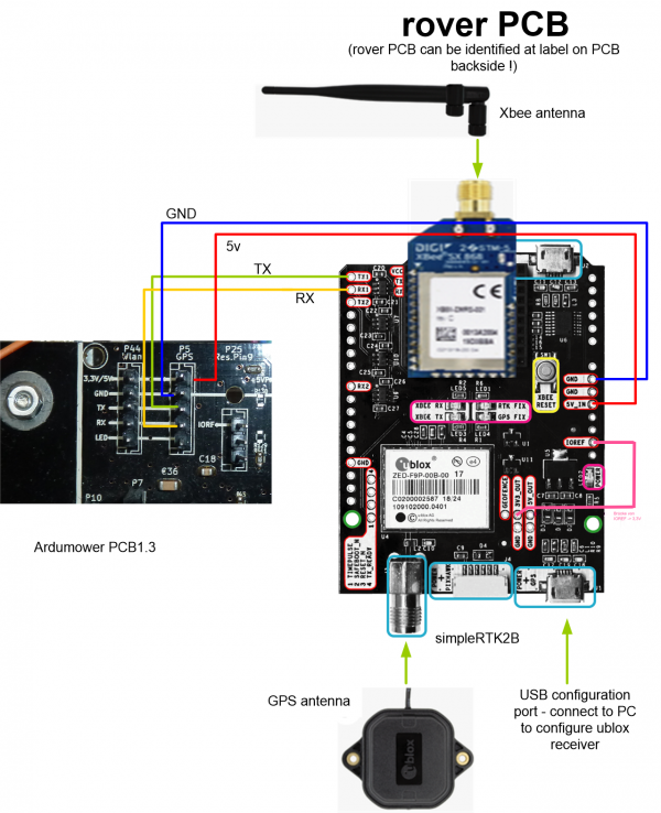
- Make sure you have the simpleRTK2B marked as 'ROVER' in your hands (look at simpleRTK2B PCB label at backside!)
- Connect XBee LongRange antenna
- Connect GPS multifrequency antenna
- Connect PCB1.3_GPS_GND to simpleRTK2B GND
- Connect PCB1.3_GPS_5V to simpleRTK2B 5V_IN
- Connect PCB1.3_GPS_TX to simpleRTK2B TX1
- Connect PCB1.3_GPS_RX to simpleRTK2B RX1
- Connect simpleRTK2B IOREF to simpleRTK2B 5V_OUT (to choose signal voltage level 5v)
Rover configuration
1. Connect SimpleRTK ROVER module via USB to your PC.
2. Download ublox u-Center and start it: https://www.u-blox.com/en/product/u-center
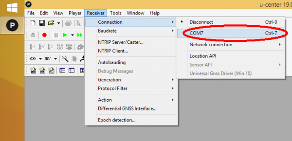
3. Choose 'Receiver->Connection' and choose your rover.
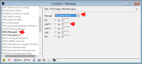
4. Choose 'View->Configuration View'. Choose configuration message 'MSG (Messages)' and select one message after the other in the list (0A-37 MON-HW3, 0A-09 MON-HW, ..., etc.). For each message, make sure the selected message is NOT activated for UART1. Example for message '01-22 NAV-CLOCK' that has been deactivated for UART1:
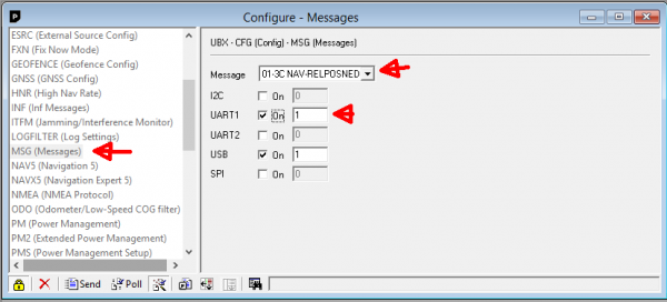
5. Finally only activate message '01-3C NAV-RELPOSNED' for UART1.
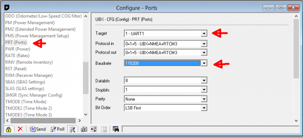
6. Choose configuration message 'PRT (Ports)' and set baudrate to 115200 for UART1:
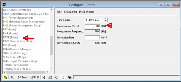
7. Choose configuration message 'RATE (Rates)' and set measurement period to 200ms (5 Hz):
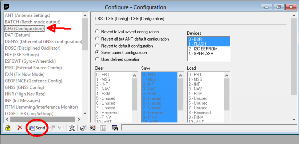
8. Choose configuration message 'CFG (Configuration)' and click on 'Send' to make the configuration in the rover persistent.
Firmware
1. Download Ardumower Sunray Firmware and unzip it: https://github.com/Ardumower/Sunray/archive/master.zip
2. Open the Arduino sketch 'sunray.ino'.
3. Start Arduino IDE, and upload the sketch to your PCB1.3.
2. After uploading, start your Ardumower - after a short while you should hear a 'beep'. Ardumower is now ready for your commands!
Phone App
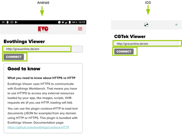
1.1. Download Viewer App:
  For Android, download Evothings Viewer: https://play.google.com/store/apps/details?id=com.evothings.evothingsviewer
  For iOS, download CGTek Viewer: https://apps.apple.com/de/app/cgtek-viewer/id1135118284
2. Start App and enter the connection URL as show below and press 'Connect':
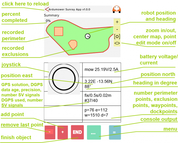
3. The App should start as shown below:
Troubleshooting
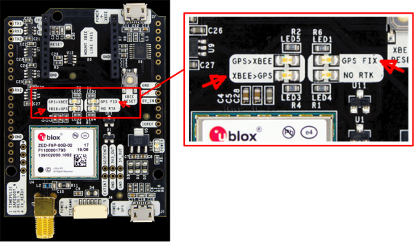
1. Once your base module is sending satellite reference data to your rover module (via the XBee LongRange modules), the LED 'XBEE->GPS' on the rover will start to blink. Verify that by turning OFF and then again ON the base module!
2. When the rover has NOT yet found its position, the the rover LED 'GPS FIX' will be OFF and the App shows 'invalid'. When the rover has found its position, the rover LED 'GPS FIX' will be ON and the App shows 'fixed'
Discussion / forum thread
- coming soon
