PID control
Inhaltsverzeichnis
Abstract
Ardumower uses a digital PID controller for
- heading/course tracking
- perimeter tracking
- motor speed control
- ...
A PID (proportional–integral–derivative) controller is a control loop feedback mechanism (controller) commonly used in industrial control systems. A PID controller continuously calculates an error value as the difference between a desired setpoint and a measured process variable.
PID controller

Examples:
- Tracking: input sensor is inside/outside, output plant is the left and right motor. Goal is to keep error (inside/outside state time) small.
- Motor speed: input sensor is odometry, output plant is the motor. Goal is to keep the error (setpoint rpm - actual rpm) small.
PID settings
The optimal P,I,D parameters depend on the actual hardware. The software default PID parameters are for the Ardumower motors available in the shop. To use your own motors, one method is trial & error (it can be difficult to find the optimum PID parameters):
- Increase P until system starts to oscillate
- Set I=0.6 * P and D = 0.125 * P
Proportional, Integral and Derivative (PID) controller concept:
P : Determines how aggressively the PID reacts to the current amount of error (Proportional)
D : Determines how aggressively the PID reacts to the change in error (Derivative)
I : Determines how aggressively the PID reacts to error over time (Integral)
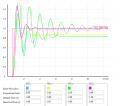
Different P,I,D parameters and their outcome

Velocity PID
The standard form is most used for position control. If you derivate the standard form, you obtain the velocity form:
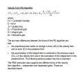
velocity PID

Simulator
For interactive learning, you can find a PID simulator here: PID simulator