Raindancer Firmware (English)
Folks, English is not my native language. If you don't understand something or find a mistake, please inform me on the forum (name: Roland) or correct the mistake by yourself. Thank you very much.
Attention! The software is still changing and can be changed / extended at any time.
Inhaltsverzeichnis
- 1 Download
- 2 Overview
- 3 For minimum commissioning, the following requirements should be met
- 4 Optional can be used
- 5 config.h
- 6 QUICK START TO MOW
- 6.1 Errorhandling
- 6.2 To get warm: Configuration of the battery service
- 6.3 Commissioning of the motors
- 6.4 Commissioning the encoder
- 6.5 Check of the closed loop control service
- 6.6 Check the position control services
- 6.7 Mowmotor commissioning
- 6.8 Perimeter Commissioning
- 6.9 Configure Bluetooth
- 6.10 Configure Arduino Central
- 6.11 First test drive
- 7 TUNE UP
- 7.1 Configure the bumpers on the bumper connectors
- 7.2 Charge Service
- 7.3 Watchdog
- 7.4 Undervoltage Shutdown
- 7.5 I2C Bus
- 7.6 RTC
- 7.7 EEPROM
- 7.8 Slow down the speed at the perimeter
- 7.9 Set mower motor current
- 7.10 Slow down when mower engine is loaded
- 7.11 Archimedean Apirale
- 7.12 Perimeter Tracking
- 7.13 Fast return
- 7.14 Mowing zones between adjacent surfaces
- 7.15 Laying the Perimeter Cable at Corners
- 7.16 Temperature Sensor
- 7.17 Shutdown Service
- 7.18 GPS Service
- 8 Perimeter Sender
- 9 Charging Station
- 10 Troubleshooting
- 11 Understanding the Behaviour Tree
Download
(On Github download the Zip-File with the green button)
The Raindancer firmware is located in the directory code\Raindancer
The transmitter firmware is located in the directory code\sender
Overview
The Raindancer firmware is based on the code of the Nucleomower which was realized with the development board STM32 Nuleo 411RE in 2016/2017. The firmware was then converted to Ardumower PCB 1.3 in 2017/2018. It pursues the goal of getting a stable system with as little hardware as possible, which works all year round and provides a good mowing result with the chaos principle.
The firmware has the following 'Workflow' : The Mower is in the charging station. The Mower drives from the charging station a predetermined distance along the perimeter to an area and then begins to mow after the chaos principle. The mowing time is approx. 130min-150min with the original Ardumowerkomponents. After the battery voltage has dropped to 23.7V, the robot looks for the perimeter cable and drives it to the charging station. Once in the charging station, the battery is charged. The next mowing operation is restarted via the mobile phone with a range command. (The robot can also be operated without a charging station.)
The firmware was developed for robots with the drive motor rear, but can also be used for the original Ardumower chassis. Optimizations for the original Ardumower chassis will be made later. The mower turns on the perimeter. If a coil has passed over the perimeter cable, the robot will continue driving for approx. 20cm. Then both coils are turned into the loop and from then on it will be further rotated at a random angle. Since the original Ardumower chassis has a short distance between spools and wheels, here is the workaround: In the config.h can be set that the mower drives back a certain way, then turns a fixed angle (rotation simulated on the perimeter) and after the turning the fixed angle, the random angle is rotated.
Internally in the firmware, distances are traveled in cm. This means that encoders are needed.
For the 'Perimeterrecognition' a 128-bit signal is used. Therefore, the Raindancer transmitter (sender) software must be installed on the transmitter. 2 perimeter receivers are needed. As you approach the perimeter cable, the robot slows down. If the robot does not recognize the signal for 2 seconds, it stops and switches off the motors. If it recognizes the signal again, it continues. If the perimeter signal is too weak in the middle of the lawn, a GPS area can be configured. If the robot is in this area, it is assumed to be within the perimeter loop.
The firmware supports a head charging station and a through charging station. Using the charging station can be switched off in the software. Then the robot stops at the perimeter when the battery voltage drops below 23.7V. For charging, the robot can then be switched off, connected to the charging cable and switched on again. The robot then goes into charging mode. If the voltage drops below 21.7V, the undervoltage trip will trip if it is not bypassed.
With the original motors and wheels, the robot drives at a speed of approx. 1200m / h. In order to get a reasonable cut, the robot has to mow about 6-9 hours a day for a 1000m² area (my experience). Of course, it also depends on the type and shape of the lawn area. For acceleration and deceleration, the Simple Trajection Planner is used by the Linux CNC project. This allows a very smooth start and braking.
If an original Bumperduino, Bumper with switches, Hall Effect sensors, ... are used, they can be connected to the Bumper Pins as before.
The firmware was optimized for 'not with the perimeter wire fenced obstacles' on the lawn. Instead of driving at full speed against the obstacle, the speed is reduced from a certain distance and drove gently against the obstacle. Prerequisite for this are sonar sensors. This feature is optional. The robot supports a self-made Bumperduino with two MaxSonar sonar sensors and an MPX5010DP FREESCALE pressure sensor for a pressure wave hose.
https://github.com/kwrtz/Raindancer/blob/master/DipTrace/DistanceBumperSensor/DistanceBumperSensor.pdf
The evaluation is done by an Arduino Nano, which is connected to the PinUserSwitch2 / 3 of the PCB1.3. Upon detection of an obstacle with the sonar sensors, the robot slows down and bumped gently against the obstacle where the bumper or bumper duino triggers. The board is relatively simple. This allows them to be easily soldered together on a laboratory board. The MaxSonar sensors can be omitted and a separate solution can be connected to the Nano. The sensor for the pressure wave hose can be omitted and only the sonar sensor is used. Another option for an approach solution is to expand the current Raindancer software. The original Ardumower ultrasonic sensors are currently not supported.
The serial interface is used for the operation. On the mobile phone is the software Arduino Central is used (free with advertising or without advertising for a few euros). In Arduino Central, buttons can be configured with commands. The operation is via command line commands. The send line must be terminated with CR. The output is automatic shown on the console or on the mobile phone, depending on where the command was just entered. Most commands are grouped by services. The group corresponds to the services mentioned in the software. The command following the service is then separated by a dot. Spaces are skipped and have no meaning. This is useful when using the mobile phone, where a space is inserted after a period.
Example: clc.enc
The service clc contains the command enc. This addresses the closes loop control service and tells it to show the encoder data.
Parameters are separated by a comma.
Example: pc.cm,60,60,30,30 //drives left wheel 60cm at 30% speed and right 60cm at 30% speed (//drives... does not belong to the command)
This addresses the Positioncontrol service. Drive 60cm at the speed of 30%
The command H displays the help..
Many commands shows an output on the console. To disable this output, you can enter h or the same command (which triggered the output). If an error or motor stall is shown, it can be reset with the reset command.
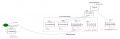
The software is modular. The individual modules are hardly influence each otherl. This makes it relatively easy to modify or extend something.
https://github.com/kwrtz/Raindancer/blob/master/Documentation/SoftwareStructure.pdf
The UMLET software was used to display and edit the Structure software.
There is a hardware abstraction layer. All communication with the hardware is done through objects in hardware.h. Most objects in hardware.h are defined in InOutInterface.h. In hardware.cpp the initialization and pin assignment of the hardware takes place. Services collect data or control the motors and make their service available to the controllogic. A behavior tree is used for the controllogic. The behavior tree accesses the services via the blackboard. Nodes of the Behavior Tree exchange information about the Blackboard.
SPLAN was used for the graphic creation of the BHT.
https://www.electronic-software-shop.com/elektronik-software/splan-70.html?language=de
To view the files of the BHT the following free software can be used:
https://www.electronic-software-shop.com/support/kostenlose-datei-viewer/?xoid=oep38ca4ehqn37a7dn3rnrpie6
The files of the BHT are here:
https://github.com/kwrtz/Raindancer/tree/master/Documentation
The robot knows two modes: Manual and Auto. In manual mode, all services are running, but the Behavior Tree (BHT) is off. In auto mode, the BHT is activated.
Which modes will start when:
MANUAL  Robot is switched on and is not in the charging station
AUTO    The robot is switched on in the charging station and detects a voltage at the charging contacts. Behavior charging is activated. The robot is loading
If the robot is in MANUAL mode, it can be switched to automode using command A. If the robot then recognizes the perimeter signal, it starts mowing.
Open points
- Stability of the software in the long term. Stand 28.04.2018 Currently, the current software version mowed 63h, has traveled 59km and has rotated 8426 times
- The line tracking algorithm has been recently optimized for the rear wheel drive chassis. Due to the short distance between coil and the wheels of the original Ardumower chassis, it may be necessary to program another algorithm.
- Optimization for the original Ardumower chassis (Mowing works very well with the workaround, if necessary, play with the parameters CONF_PER_CORRECTION_ANGLE and CONF_PERIMETER_DRIVE_BACK_CM)
- Use RTC to program start at a defined time
Other wishes
- Integrate rain sensor
- The charging station is currently only counterclockwise approached.
- Amplify the signal of the charging station to + -20V voltage stroke
- SRF08 integration
- Integrate I2C temperature sensors
- An external start / stop button that starts or stops mowing
- Approachthe charging station with GPS. Drive 15m before the charging station on the perimeter and then drive into the charging station..
- GPS Map - Note where mower has already mowed. Then mow in less mowed areas if necessary.
The GPS card will probably have to be outsourced to an external processor
For minimum commissioning, the following requirements should be met
![]() Safety note: For safety reasons, the mower blades must not be mounted during the first tests!
Safety note: For safety reasons, the mower blades must not be mounted during the first tests!
![]() Important: For the first gearmotor tests, the robot should be jacked up so that the wheels are not in contact with the ground!
Important: For the first gearmotor tests, the robot should be jacked up so that the wheels are not in contact with the ground!
- PCB1.3 with Arduino DUE
- Original Ardumower drive motors with encoder
- Original Ardumower mowing motor
- Two Ardumower perimeter coils front left / right. Mounted on original Ardumower chassis if necessary: Left / center (depends on which line tracking algorithm one uses)
- BT module
- The bridge for the encoders on the PCB1.3 is bridged to the 2-divider.
- 24V power supply
Optional can be used
- RTC with EEPROM
- Ardumower Bumper Pins with switches, Hall effect sensors, original Bumper Duino, ...
- Pass through charging station
- Self-built Bumperduino with 2MaxSonar sensors on PinUserSwitch2 / 3
config.h
The file config.h contains the basic configuration of the firmware.
'Before commissioning the parameters must be adjusted.'
Select the chassis form. Only one parameter may be set to true.
#define ARDUMOWER_CHASSIS  true
#define PARANELLO_CHASSIS  false
#define RAINDANCER_CHASSIS false
In config.h go then to the code section, which belongs to your choice and change this section. For the Ardumower chassis the section starts with following:
//======================================================================================================================
// CONFIG FOR ARDUMOWER CHASSIS
//======================================================================================================================
Console Speed:
#define CONF_PC_SERIAL_SPEED 115200 // Speed serial consol
If the Bluetooh module has already been configured with the Azurit firmware, the line
#define CONF_BT_SERIAL_SPEED 115200
has to be changed to:
#define CONF_BT_SERIAL_SPEED 19200
Setting the wheel circumference and wheel distance. The original Ardumower wheel has a circumference of 78.54f cm
#define CONF_RADUMFANG_CM			80.738f // Wheel circumfence in cm original ardumower: 78.54f
#define CONF_DISTANCE_BETWEEN_WHEELS_CM		36.0f	// Distance where the wheels hits the ground do not measure on top of the wheels!!!
For the first startup most services should be disabled to prevent error messages:
#define CONF_ENABLEWATCHDOG             	false   // Set to false to disable Watchdog. true to enable.
#define CONF_DISABLE_RANGE_SERVICE		true    // Disables my own range sensor running on bumper duino on pinUserSwitch3 => diNearObsacleSensor
#define CONF_DISABLE_BUMPER_SERVICE		true   // Disables original bumper sensor pins (PCB1.3) on pinBumperLeft => diBumperL and  pinBumperRight => diBumperR
#define CONF_DISABLE_BUMPERDUINO_SERVICE	true   // Disables my own bumper duino sensor on pinUserSwitch2 => diBumperSensor
#define CONF_DISABLE_PERIMETER_SERVICE	        false   // Disables perimeter sensor
#define CONF_DISABLE_RTC_SERVICE		true    // Disables rtc sensor
#define CONF_DISABLE_EEPROM_SERVICE		true    // Disables EEPROM requests
#define CONF_DISABLE_BATTERY_SERVICE	        true    // Disables battery sensor
#define CONF_DISABLE_CHARGE_SERVICE		true    // Disables charge system service
#define CONF_DISABLE_RAIN_SERVICE              true    // Disables rain sensor
#define CONF_DISABLE_DHT_SERVICE               true    // Disables temp sensor
#define CONF_DISABLE_GPS                       true    // Disables GPS service
#define CONF_DISABLE_MOTOR_STALL_CHECK         true    // Disables the motor stall/encoder check in closed loop control
#define CONF_DISABLE_MOW_MOTOR                 false   // Disables the mow motor
#define CONF_DISABLE_CHARGINGSTATION true
'ONLY for the original Ardumower chassis design' the following constants should be set to optimize the rotation at the perimeter
#define CONF_PER_CORRECTION_ANGLE       30
#define CONF_PERIMETER_DRIVE_BACK_CM    40.0f
Since compiling is done more often, it makes sense to jack up the robot so that the drive wheels and the mower motor can rotate freely.
After the first compile, upload and start of the firmware, the last line should be:
Press H for help.
Enter H here. Thereafter, all available commands are displayed. It is a good ideas to copy and save the commands to a file, so that you can look at it when you need.
If after compilation following warning occure, they can be ignored:
pinman.cpp: 18:0: warning: "PWM_FREQUENCY" redefined [enabled by default]
  #define PWM_FREQUENCY 3900
pinman.cpp: 19:0: warning: "TC_FREQUENCY" redefined [enabled by default]
  #define TC_FREQUENCY 3900
QUICK START TO MOW
The aim of this chapter is to become more familiar with the operation, and to configure the robot to the extent that the perimeter sensors work and you can mow within the perimeter.
The robot is connected via the console cable. Speed: 115200
Errorhandling
If the firmware detects an error, this goes into the Errormode. The Mower stops and the mow motor is switched off. The services continue to run. The first error occurred is latched. The error is then sent to the console or bluetooth (BT) every 2 seconds, depending on what was last active or activated by sending a character. If you has started the mower via Bluetooth, the error is then shown on BT.
To disable the error, the following commands must be entered one after the other:
reset     //reset error and motor faults
M         //activate manual mode
The error command can be used to display the error log. The error log shows the history of the traversed running nodes of the BHT as well as various other events. It is 5000 characters tall.
error //show errormessage
The show.hist command displays the last direction of rotation and other parameters.
show.hist //show history
The last entered values will be displayed first, so that they are above!
After disabling the error, the Mower can be started again with:
A
However, both coils must be in the perimeter for that.
To get warm: Configuration of the battery service
The battery service determines the voltage of the battery and makes it available to the BHT.
Activate the battery service in config.h and then re-install the software.
#define CONF_DISABLE_BATTERY_SERVICE false
Enter the command: bat.show It should display the correct battery voltage.
If this deviates by more than 0.2V, then this can be adjusted with the constants #define BATTERYFACTOR_BS 11.0f // Equivalent to (100 + 10) / 10 Voltagedivider #define DIODEDROPVOLTAGE_BS 0.4f These constants are defined in batterySensor.h.
The voltage in batterySensor.h is calculated as follows
sensorValue = aiBATVOLT.getVoltage();
float readVolt = sensorValue * BATTERYFACTOR_BS + DIODEDROPVOLTAGE_BS; // The diode sucks 0.4V
Commissioning of the motors
The first thing to check is whether the motors are turning and whether they are turning in the right direction. For this purpose, the motors are controlled directly with a PWM specification. This means, there is no control of the speed based on the encoder. The speed control loop is open (open loop);
The command clc.mt, 1,150 causes the clc service to send the input PWM of 150 directly to the motor. Maximum for the PWM is 255. A 1 controls the left engine, a 2 the right.
Enter the command:
clc.mt,1,150
This activates the motor (1) on the left directly with a PWM of 150. The wheel is then Stopped with:
clc.mt,0,0
The wheel on the left should turn forward. If it turns backwards, the cable at the plug must be reversed. Should the wheel not turn, it can still be tried with a higher PWM of e.g. 200. The wheel should definitely turn even at a PWM of 50 (better less).
The same for the right wheel (2):
clc.mt,2,150
The wheel is then Stopped with:
clc.mt,0,0
Anmerkung:
Die PWM für die Motoren läuft mit 3900Hz.
Wenn man die Originalwerte verwenden möchte, muss man nachfolgende Zeilen in pinman.cpp abändern.
#define PWM_FREQUENCY 3900
#define TC_FREQUENCY 3900
Achtung: Wenn die PWM zu hoch gesetzt wird, z.B. 18000Hz, dann drehen sich die Räder bei niedriger PWM von z.B. 60 nicht mehr. Es kommt dann ein Fehler, dass bei Vorgegebener PWM von 60 die Geschwindigkeit 0 ist.
Commissioning the encoder
It it checked if the encoders work and if they count in the right direction.
The encoder routine has two counters per wheel. Once an absolute counter (absEnc), which always counts positive no matter in which direction the wheel turns. And a positive / negative counter (enc), which counts up when driving forward and counts down when reversing.
Enter the command
clc.mt, 1,150
to make the left wheel turn.
Enter then
clc.enc
This will display the encoder values from the left and right wheels.
The output is terminated with the command: h.
Both displayed counters of the left wheel (1) must now count up.
Example:
Engine 1 = left - should not count if only the right engine is running.
Engine 2 = right - should not count if only the left engine is running.
! 03, motor 1 enc: 972 absEnc: 972 rpm: 2.596326 m / h: 125.773315 deltaTicks: 2 deltaTime: 32986us
! 03, motor 2 enc: 974 absEnc: 974 rpm: 3.325853 m / h: 161.113647 deltaTicks: 2 deltaTime: 33445us
! 03, motor 1 enc: 974 absEnc: 974 rpm: 2.923552 m / h: 141.625061 deltaTicks: 2 deltaTime: 33156us
! 03, motor 2 enc: 975 absEnc: 975 rpm: 2.678638 m / h: 129.760696 deltaTicks: 1 deltaTime: 33144us
! 03, motor 1 enc: 976 absEnc: 976 rpm: 3.132316 m / h: 151.738159 deltaTicks: 2 deltaTime: 32857us
! 03, motor 2 enc: 976 absEnc: 976 rpm: 2.296233 m / h: 111.235962 deltaTicks: 1 deltaTime: 32859us
! 03, motor 1 enc: 978 absEnc: 978 rpm: 3.251686 m / h: 157.520752 deltaTicks: 2 deltaTime: 32998us
The example shows that the encoders are counting up. 'Example motor 1' : enc: 972 then enc: 974, then enc: 976 ... 'Example motor 2' : enc: 972 then enc: 975, then enc: 976 ...
If the enc value counts negative when driving forward you can configure it in the config.h:
#define CONF_LEFT_ENCODER_INVERSE false
#define CONF_RIGHT_ENCODER_INVERSE false
To do this, set CONF_LEFT_ENCODER_INVERSE to true for the left wheel. Set CONF_RIGHT_ENCODER_INVERSE to true for the right wheel.
Do the same for the right wheel:
clc.mt, 2,150
Command is stopped with clc.mt, 0,0.
After the lines in the config.h have been set correctly, recompile, play and retest!
Check of the closed loop control service
The closed loop control (clc) service controls the speed of a wheel and thus also the straightforward movement of the robot. There is one service for each wheel so there are two services in total. The service internally calculates the speed of the wheel with the aid of the encoder values and then sets the necessary PWM to reach the specified speed (closed loop). The speed is given in%. 100% refering to the constant CONF_MAX_WHEEL_RPM in the config.h.
With the command clc.v,30 both services are commanded to turn the wheel at a speed (v) of 30%. Thus, both wheels should turn forward.
Enter:
clc.v, 30 Moving forward with speed 30%
then
clc.v, s stop engine
then
clc.v, -30 drives reverse with speed 30%
If everything is working, then continue. Otherwise check encoders and drivedirection again.
mot.cur Shows the motor current.
Check the position control services
The Position Control Service (pc) is used to drive the wheel a certain way or to turn the wheel a certain angle. There is one service per wheel. With the command pc.a,360,80 both wheels are comanded to: Turn the wheels an angle of 360 degrees with a maximum speed of 80%.
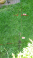
Make a mark on a wheel to see how far it turns.
pc.a, 360,80  Rotates both wheels forward by 360 degrees with 80% speed if everything is configured correctly.
pc.a, -360,80 Rotates both wheels backwards by 360 degrees with 80% speed if everything is configured correctly.
The Position Control can be stoped with the command
pc.s
If the wheel does not turn 360 degrees, the value CONF_ENCTICKSPERREVOLUTION in config.h appears to be wrong. For the original engines from the Ardumower shop, the value of 1060 is given.
In addition, the constant CONF_RADUMFANG_CM is important for the calculation to be correct to drive a particular path in cm.
Since the engine monitoring was switched off in the beginning in the config.h, it is now time to switch on again. Motor monitoring checks whether the encoders deliver values when the motors are turning, whether they are turning in the right direction, or whether the motor is actually turning when a PWM is applied.
To enable motor monitoring in config.h, set the value CONF_DISABLE_MOTOR_STALL_CHECK to false.
#define CONF_DISABLE_MOTOR_STALL_CHECK false
Recompile and upload. Then try again. No errors should be displayed.
If everything works, the robot can be put on the wheels.
Further tests can still be performed (note that the USB cable should be long enough, preferably use an extension);
Drive a certain way in cm
pc.cm,60,60,30,30 drives 60cm forward with the speed of 30%
pc.cm,-60,-60,30,30 drives 60cm backwards with the speed of 30%
Turning a certain angle. Prerequisite: CONF_ENCTICKSPERREVOLUTION, CONF_RADUMFANG_CM and CONF_DISTANCE_BETWEEN_WHEELS_CM are configured correctly.
turnto, 360,30 Turn the robot 360 degrees CW (clockwise)
turnto, -360.30 Turn the robot 360 degrees CC (counter clockwise)
If the robot does not turn 360 degrees, the constant CONF_DISTANCE_BETWEEN_WHEELS_CM in config.h is probably wrong.
Mowmotor commissioning
The mowing motor does not use an encoder. It is operated with a PWM of 255. The PWM of 255 is not immediately given to the engine. It ramps up the PWM from 0 to 255. The same applies to the braking of the engine. It may happen that a motor fault is displayed when the engine is decelerating. This is because the inertia of the mowmotor disc tends to continue to rotate the motor, thus retroactively injecting a current into the motor driver that exceeds the limits such that the tri-state outputs of the driver go to high-impedance. If this happens, the error can be reset with the reset command.
Befehl eingeben:
z //mow motor start
danach
t //mow motor stop
It may be that when stopping the motor a fault comes up. Reset this with the command reset.
mot.curm //indicates the mowing motor current.
If the PCB1.3 is used, the mower motor current is probably displayed incorrectly here. See: Adjusting the mower motor current in Tune Up
This can be done later and is not so important for the first mowing operation.
Perimeter Commissioning
The Raindancer firmware works with two coils. This determines the angle at which the robot meets the perimeter. Accordingly, it is decided whether CC or CW is rotated. The perimeter signal must be received all the time while mowing. If the signal is not received for 2 seconds, the robot will stop and continue as soon as the signal is received again. The time that a non-receive is tolerated is set with the parameter CONF_PER_SIGNAL_LOST_TIME in the config.h. With this it is possib to bridge "Receiving holes" in the middle of the lawn. Disadvantage is, if the transmitter fails exactly when the robot is at the perimeter, it may be that the robot travels this set time outside the perimeter loop.
Prerequisite for commissioning: The spools of the robot must be within the perimeter loop for commissioning. The Raindancer transmitter firmware must be installed on the transmitter.
First check is if the signal is detected.
You can see the calculated value of the individual coils as follows:
per.resultl for left coil
and
per.resultr for right coil.
The example below shows that the BAD has not received a valid signal. It is important here that no BAD is displayed. The received amplitude is behind mag :. The signal quality can be seen on the Peak Signal Noise Ratio psnr.
Beispiel per.resultl
mag:  453  peak @ 432 :  453   peak2 @ 328 :  142   MSE: 1704.569   psnr:  120.388   psnr2:   11.829   ratio:   10.177
mag:  431  peak @ 279 :  431   peak2 @ 145 : -125   MSE: 1638.841   psnr:  113.349   psnr2:    9.534   ratio:   11.889
mag:  372  peak @ 128 :  372   peak2 @  12 :  119   MSE: 1521.076   psnr:   90.978   psnr2:    9.310   ratio:    9.772
mag:  458  peak @ 486 :  458   peak2 @ 352 : -195   MSE: 1922.495   psnr:  109.110   psnr2:   19.779   ratio:    5.516
mag:  428  peak @ 335 :  428   peak2 @ 233 :  118   MSE: 1818.376   psnr:  100.740   psnr2:    7.657   ratio:   13.156
Beispiel per.resultr
mag:    6  peak @ 144 :    6   peak2 @  24 :   -5   MSE:    3.161   psnr:   11.388   psnr2:    7.908   ratio:    1.440    BAD
mag:   -5  peak @ 161 :   -5   peak2 @  46 :    4   MSE:    2.380   psnr:   10.504   psnr2:    6.723   ratio:    1.562    BAD
mag:   -5  peak @  60 :   -5   peak2 @ 179 :    5   MSE:    3.556   psnr:    7.030   psnr2:    7.030   ratio:    1.000    BAD
mag:    5  peak @ 159 :    5   peak2 @   3 :    4   MSE:    2.949   psnr:    8.477   psnr2:    5.425   ratio:    1.563    BAD
mag:    5  peak @  11 :    5   peak2 @ 153 :    5   MSE:    3.286   psnr:    7.607   psnr2:    7.607   ratio:    1.000    BAD
End the output with h.
Both coils should detect the signal, so do not indicate a BAD. Also not sporadicly!
Next, the polarity of the signal must be configured. Enter:
per.show. (switch off output with h)
If the coil is inside the perimeter, the amplitude of the coil must be positive.
The detected perimeter amplitudes are now shown. ML indicates the amplitude of the left coil, MR the amplitude of the right coil.
!03, ML: -305  MR: 331 magMax:332 magMedL%: 0 magMedR%: 102
!03, ML: -330  MR: 338 magMax:332 magMedL%: 0 magMedR%: 102
!03, ML: -327  MR: 330 magMax:332 magMedL%: 0 magMedR%: 102
!03, ML: -336  MR: 332 magMax:332 magMedL%: 0 magMedR%: 102
!03, ML: -304  MR: 328 magMax:332 magMedL%: 0 magMedR%: 102
!03, ML: -326  MR: 324 magMax:332 magMedL%: 0 magMedR%: 102
However, one can see here that the magnetude on the left coil is negative. Inside the perimeter loop, this must be positive.
This can be set in the config.h:
#define CONF_LEFT_COIL_INVERSE		true
#define CONF_RIGHT_COIL_INVERSE        false
After new compiling, the values should be positive.
Attention, with per.resultl and per.resultr, the sign of the amplitude is displayed as actually received, regardless of the settings in CONF_LEFT_COIL_INVERSE and CONF_RIGHT_COIL_INVERSE.
It may be that per.resultl provides a positive amplitude and per.resultr a negative amplitude inside the perimeter. That's OK, since it depends on the connection of the coils. Conversion with CONF_LEFT_COIL_INVERSE / CONF_RIGHT_COIL_INVERSE takes place later in the software.
It is important to configure CONF_LEFT_COIL_INVERSE and CONF_RIGHT_COIL_INVERSE so that per.show displays positive amplitudes within the perimeter.
Configure Bluetooth
If the module has already been configured with the original Ardumower software, can CONF_BT_SERIAL_SPEED=19200 be set.
#define CONF_BT_SERIAL_SPEED 19200
(The perimeter outputs are extremely large.) It may be that the software faltered at this transfer rate when viewing perimeter data over BT at that baud rate.) This would be the configuration then done.
Since there are sometimes problems with the configuration of BT modules, I suggest to reprogram a working BT module only if you have another working BT module in reserve.
For the configuration of the BT the original Ardumower routine is used. However, the baud rate is set to 115200.
Therefore, you can use the tips used for troubleshooting in the forum.
Lets start:
De-energize the PCB (also disconnect USB from the DUE). Press and hold button on BT module. Turn on the board.
The BT module should now flash every 2 seconds.
Release the button. Reconnect the USB to the DUE. The BT module should still be flashing every 2 seconds.
Now try bt.show first, to see if the BT module is found:
bt.show
If found successfully put in the command:
bt.set
The BT module will now be configured.
Configure Arduino Central
The software runs on an Android mobile phone or tablet. Arduino Central can be downloaded from the Play Store. Another software that works is Serial Bluetooth Terminal.
In Arduino Central, the top right menu (three points) can be opened. Call Settings there.
Then open the button layout Configuratin. Here you can set which buttons are displayed. Only the following should be selected:
Show Control Button
Show Standard Button set 1
Show Standard Button set 2
Show Standard Button set 3
Go back and open Serial Terminal Settings Set Terminal View Character Limit to 10000
Go back and select Line Ending for Commands
Select CR
Go back and select Line Ending for Incoming Data
Select NL
Then first go out completely from the menu.
First, the BT module must now be paired to work with the mobile phone. That means on the phone enable BT. Then go to the BT menu on the phone and look for new devices. There should then appear a new device. Select this device and pair. There is a password query which is 1234 or 0000 Thereafter, the module is included in the device list
Now in the menu of Arduino Central go to connect to device and click the BT of the mower. If everything was successful, BT connect should be displayed at the top right.
At the command line, type H and Send. Then the help should be displayed.n.
In Arduino Central commands can be stored under the menu item Standard Button Setup. Currently I have deposited the following commands with me:
Button 1 Text: Manual 	Command: M
Button 2 Text: Auto   	Command: A
Button 3 Text: Hide   	Command: h
Button 4 Text: area,19 	Command: area,19
Button 5 Text: gohome 	Command: gohome
Button 6 Text: per 	Command: per.show
Button 7 Text: mowense 	Command: mot.curm
Button 8 Text: bat 	Command: bat,show
Button 9 Text: charge 	Command: charge.show
These commands can be customized as needed.
First test drive
For safety reasons, switch off the mowmotor in config.h for the first test.
#define CONF_DISABLE_MOW_MOTOR true
Then recompile and upload software.
Attention, there are still no bumpers active! That the area inside the perimeter must be free.
Disconnect the USB cable and connect to Arduino Central.
Put the robot inside the perimeter loop.
Check the perimeter signal again with show.per. Disable perimeter output with h or show.per output
A enter for auto mode to start the mowing.
It may take 5 seconds for something to happen. The robot first drives up the mowmotor. Since this one is turned off, it may look like it does not happen.
M enter for manual mode to stop the robot.
TUNE UP
Configure the bumpers on the bumper connectors
The original Ardumower chassis does not provide a standard solution for bumpers. Since most users create their own solutions here, the firmware has some options to configure the bumper service for their own needs.
To enable the bumper, the following line must be configured in config.h:
#define CONF_DISABLE_BUMPER_SERVICE false
To test bumpers, you can use the bumper.show command. The bumper service then plays its activity on the console or mobile phone, depending on where that command was sent from.
bumper.show
The bumper pins are configured by default as inputs with pullup resistor. This means, the input is high by default as long as the pin is not connected to GND by a switch for example.
The bumper service can be configured with following parameters in config.h:
Using the left or/and right bumper
#define CONF_USE_LEFT_BUMPER            true     // left bumper is used
#define CONF_USE_RIGHT_BUMPER           true     // right bumper is used
Determine if the bumper is aktive if the pin is connected to GND:
#define CONF_LEFT_BUMPER_LOW_ACTIVE     true     // left bumper is activated when pin is low
#define CONF_RIGHT_BUMPER_LOW_ACTIVE    true     // right bumper is activated when pin is low
If one uses a left and a right bumper, there is still the possibility to configure that the direction of rotation is determined by the activated bumper after driving back. That means, that when the left bumper is pressed, the robot then turns right after driving back.
#define CONF_ESCAPEDIR_DEPENDING_ON_BUMPER false  // if set to true, the robot rotates in the opposite direction of the activated bumper. If false, the escape direction is random.
                                                  // only set to true if you use a bumper for left and a bumper for right.
The bumper pins are configured by default as inputs with pullup resistor in hardware.cpp:
DigitalIn diBumperL(pinBumperLeft, true);
DigitalIn diBumperR(pinBumperRight, true);
This means the input is high by default if the pin is not pulled to GND.
If you want to switch off the pull-up resistors, the lines must be changed as follows
DigitalIn diBumperL(pinBumperLeft, false);
DigitalIn diBumperR(pinBumperRight, false);
Charge Service
The charge ervice provides the BHT with the charge voltage and the charge current. It contains functions for switching the charger relay on / off.
Annotation:
If the Mower is switched off (battery not connected) and then a charging voltage is connected to P42 Charger,
the board is directly supplied with voltage via D73. The problem is that the capacitors on the board have no voltage and supply a short circuit when connected. Then a 1.6A fuse will break through in EF1.
Therefore, EF1 should be 5A.
I've removed the D73 from my board, because I think it's only reasonable if the battery is so empty that the board and Relay no longer works with the battery. If this really
happens, I will charge the battery directly with the charger. This should be happen only in case of an error and should not be the rule (but I would not persuade anyone to do this too).
Furthermore, the D73 has a different potential on the back, as the diodes are soldered behind this. Since it makes sense to separate them with hot glue, not that they come together.
The following describes how to load the robot.
Independent driving in the charging station
When the robot moves into the charging station, the charging relay is switched off. At this time, only the voltage of the charging station is at the contacts. If the robot has detected this, it stops, waits two seconds and checks the charging voltage again. If this is OK, it moves 3cm forward, 3cm backwards and again 2cm forward. This serves to optimize the connection to the charging contacts (which are currently designed as sliding contacts). Then the relay is switched on and the charging voltage checked again. (This behavior can easily be reprogrammed in the BHT.) The relay remains energized and thus the battery is connected to the charger until the robot is commanded to go to an area or the robot is switched to manual mode or switched to auto mode.
Use without charging station
To load the robot it should be in manual mode (enter command M). Then you can use charge.relay,1 to switch on the relay and with charge.relay,0 to switch off the relay. The relay automatically turns off when the Auto mode is activated. The relay only switches on if the charging voltage is applied to the charging contacts!. Another possibility is to connect the charging contacts when switched off and then turn on the robot. The robot then goes into auto mode and turns on the Behavior Charging Station. He now thinks he is in the charging station.
Put in the charging station
Here, put the robot in the switched off state in the charging station, so that the charging contacts have contact. Then turn it on. The robot then enters the charging mode in the Behavior Charging Station. He now thinks he is in the charging station, turns on the relay and charges.
To enable the charging service, set the config.h CONF_DISABLE_CHARGE_SERVICE to false and re-install the software.
#define CONF_DISABLE_CHARGE_SERVICE false
Enter the command:
charge.show
This continuously displays the voltages and currents. Currently everything should be displayed with 0.
Connect charger to P42 or charging contacts.
Now you should see the Charge Voltage (CV)..
Enable relay:
charge.relay,1
Now a current flows from the charger to the battery and a charge current is displayed (CC).
Disable relay:
charge.relay,0
Testing in the off state via the console:
Turn on the robot and connect USB. Wait until software has started up. Connect charging contacts. Open the serial console. The DUE restarts. The relay should be energized and the console output at boot should show "Charging station detected". The robot has now switched to the Chargingbehaviour.
Enter M to return to manual mode and switch off the relay.
Watchdog
The watchdog is solely for safety. If the software hangs, the watchdog should prevent the robot from running unchecked. The watchdog is hardware implemented in the DUE. It is activated in the config.h with:
#define CONF_ENABLEWATCHDOG true
Each time the loop is traversed, the watchdog will be reseted with the function call watchdogReset ();.
If watchdogReset (); is not called within 3 seconds (because the software hangs somewhere), the DUE is restarted, stopped the engines and the software goes into manual mode.
Annotation: Since the variables of the firmware are reinitialized during the reboot, it is difficult to find out what the cause of the error is. The Mower simply stops, and one wonders when opening the BT connection, that everything is fine and no error is issued - except that the software is in manual mode.
Undervoltage Shutdown
The undervoltage shutdown is used to prevent the battery from falling below a certain voltage and then deeply discharged. The implementation of the undervoltage shutdown is implemented in the battery service. Prerequisite is, that the jumper 8 UV shutdown on PCB 1.3 is set to Auto. If you then put voltage on the board, this gets no electricity first. Therefore, when switching on the voltage, the UV shutdown must be bridged with the P20 button. Then the PCB1.3 gets voltage. This button should be held for 4 seconds. Then the software takes control of the UV shutdown. The P20 button must then be open again, otherwise the software can not switch off the voltage.
In config.h the threshold is set at which the voltage is switched off
#define CONF_VOLTAGE_SWITCHOFF_BS 21.7f
If the battery voltage falls below this voltage for one minute, the voltage to PCB1.3 and the motors will be cut off. The entire PCB1.3 is then dark.
If you want to bridge the undervoltage cut-off, you can set jumper 8 to permanent-on or bypass P20. I have an on / off switch connected to the P20, so that I can bridge this for testing purposes. The jumper 8 is still on auto.
I2C Bus
The I2C bus can be scanned with the command i2c.scan. All found addresses will be displayed.
i2c.scan
The addresses of the RTC module and the EEPROM can be adjusted in the hardware.cpp. Currently the following default addresses are configured:
byte DS1307_ADDRESS = B1101000;
byte AT24CX_ADDRESS = B1010000;
RTC
The RTC module is currently not used. It is intended to use this later for a time mowing start. However, the RTC module can already be programmed and tested.
The RTC module is activated with the following line in the config.h:
define CONF_DISABLE_EEPROM_SERVICE false
The following commands are available:
rtc.show          //show rtc values every rtc read (10sec)
rtc.config        //show rtc service config
rtc.find          //tries to find RTC and show result
rtc.set,8,17,3,25,01,2017 //set rtc time=8:17 dayOfWeek=3 date=25.01.2017
EEPROM
The EEPROM is used on the RTC. Currently it is used to store statistics. The following statistics are stored: total mowing time, total distance traveled, total number of rotations, number of loading operations.
The use of the EEPROM is switched on with the following line in the config.h:
#define CONF_DISABLE_EEPROM_SERVICE false
The following commands are available for the EEPROM:
eep.config           //show EEPROM service config
eep.u8t,10           //show uint8_t at address 10
eep.s32t,10          //show int32_t at address 10
eep.f,10             //show float at address 10
eep.set.u8t,10,7     //write value uint8_t=7 to address=10
eep.set.s32t,10,1234 //write value int32_t=1234 to address=10
eep.set.f,10,7.3     //write value float=7.3 to address=10
eep.erase            //erase the eeprom
To test the EEPROM e.g. enter the following command:
eep.set.f,10,7.3
This writes the float value 7.3 to the addresses 10, 11, 12, 13 in the EEPROM.
With the command
eep.f,10
the value can then be read out again.
The command eep.erase deletes the first 3 pages of the EEPROM. The other pages are currently not deleted because they are not used.
eep.erase
It makes sense to erase the EEPROM after the enable the service so that the memory cells are initialized.
Slow down the speed at the perimeter
The Mower drives at a speed of 1200m / s. In order to make the deceleration a bit gentler when driving over the perimeter, the robot reduces the speed just before the perimeter (about 20 cm).
The following constants in the config.h affect recognition near the perimeter:
#define CONF_NEAR_PER_UPPER_THRESHOLD   80.0L    // Threshold of one coil where Perimetersignal is detected as near perimeter
#define CONF_NEAR_PER_LOWER_THRESHOLD   70.0L    // Threshold of the other coil where Perimetersignal is detected as near perimeter
To determine if the robot is close to the perimeter, the amplitude of the left and right coils are evaluated. For this purpose, the firmware determines the current maximum amplitude over the entire travel time of the Mower. Now, when the left coil reaches an amplitude of 80% (CONF_NEAR_PER_UPPER_THRESHOLD) or higher of the maximum value and the right coil reaches above 70% (CONF_NEAR_PER_LOWER_THRESHOLD) or higher of the maximum value, it is assumed that the robot is close to the perimeter. The same applies if the right coil reaches 80% and the left 70%.
These values depend on the kind of coil used and on the signal strength of the transmitter and therefore may need to be readjusted.
To adjust this, enter the command per.show while the Mower is driving.
per.show
If the mower then runs over the perimeter wire enter the same command or press h. Then scroll back in the display and look at the values.
Example: !03, ML: 305 MR: 331 magMax:332 magMedL%: 73 magMedR%: 87
The values magMedL%: 73 magMedR%: 87 indicate here the measured percentage of the coils 20cm before the perimeter wire. Use this percentage as starting point to set CONF_NEAR_PER_UPPER_THRESHOLD and CONF_NEAR_PER_LOWER_THRESHOLD. Several tests should be carried out for the determination. Better to slow down a little earlier than to slow down too late. The difference between UPPER and LOWER has been introduced because the coils do not have always the same value, e.g. when the Mower is running obliquely or almost parallel to the perimeter.
It may be that magMedL% and magMedR% show more than 100%. This is based on the type of magMax determination and is OK.
The calculation is stored in the function 'bool TPerimeterThread :: isNearPerimeter ()' in the file perimeter.cpp.
Set mower motor current
It should be noted that the outputs of the mowing motor driver on PCB1.3 have been interconnected.
With a PWM of 255 at the mower motor almost no current is measured on my board. I have then remeasured the value with a multimeter. I measure at M2 FB at full speed and free-wheel only 0.04V. Correct value would be about 0.22V because the engine pulls here 0.41A. On M1 M1 I measure a voltage of 0.007V. It seems that the current measurement is no longer correct due to the parallel connection. One might think that this should be halved. But it is not like that.
An interconnection of the two MC33926 is not recommended by the manufacturer and seems to provide an incorrect current measurement.
https://www.nxp.com/docs/en/application-note/AN4833.pdf
Quote:"If two independent H-bridges are used (separate MC33926 or similar), the load sharing may not be quite as even,
resulting in a reduction in maximum drive capability. This configuration will latch any fault until the EN pin is toggled."
I have then disconnected from the Mowmotor driver pins M1 OUT1 and M1 OUT2 (bent and guided next to the socket connector, so that they have no contact). Now the current measurement works properly, but under 1A this is not really accurate. Only from 1A the value is reliable.
If M1 OUT1 and M1 OUT2 are not disconnected, the measured and displayed current too low.
Therefore, the scale value for the correct current measurement must be adjusted in the setup function of the class TMowMotorSensor in the file mowmotorSensor.h.
The scale factor should be set at currents around 1A or more. Therefore he mower disc must be loaded with resitance when measuring the current with the multimeter.
If M1 OUT1 and M1 OUT2 are disconnected, the factor whih is set by default and find out by measuring is probably reasonably correct. However, this can only be checked by measuring current levels of 1A.
The measured current and wattage are displayed with the command:
mot.curm
Slow down when mower engine is loaded
When the mower motor is loaded, the mower slows down.
From which wattage of the mower motor the mower is slowed down, can be configured in the config.h with the parameter
#define CONF_MOW_MOT_UNDER_LOAD 30.0f
If the mower needs more than 30W, the speed will slow down.
The current watts number when mowing can be displayed with the command:
mot.curm
Thereafter, the value can be set at its discretion.
Attention, the motor drivers deliver an accurate current measurement only from 1A on (according to data sheet 0.5A). That Values where the current is displayed under 1A are inaccurate and should not be used. The accuracy is according to data sheet at a current of over 0.5A + -20%.
The speed setting code is in the class class TCruisePerimeterNear: public Node in the bCruise.h file.
Furthermore, it must be taken into account that the outputs of the mower motor driver have been interconnected. This is not recommended by the manufacturer and provides incorrect current measurement.
Archimedean Apirale
If the mower motor is loaded, an Archimedean spiral can be activated. It starts with a small curve at the start, so that the inner wheel turns. Therefore, a small tuft of grass will remain in the middle of the spiral.
The spiral is activated in the config.h with the following line:
#define CONF_ACTVATE_AUTO_SPIRAL true
The parameters listed below can be customized as desired. If the spiral is turned too often, the robot will not get off the ground and will only work one area of the lawn.
The following parameters in the config.h affect the activation of the spiral:
#define CONF_MOW_MOT_UNDER_HEAVY_LOAD_ON   45.0f  //If mow motor Watt is over this value, it is assumed that the motor is under heavy load.
#define CONF_MOW_MOT_UNDER_HEAVY_LOAD_OFF  30.0f  //If the mow moter is under heavy load, the measured watt must come under this value to reset heavy load.
#define CONF_MOW_MOT_UNDER_LOAD            30.0f  //The mow motor is under load, if this Watt is measured.
The implementation of the spiral activation is in the file: bCruise.h Class: class TCruisePerimeterNear: public Node
The code for activation is as follows:
if(CONF_ACTVATE_AUTO_SPIRAL) {
(a) if(bb.mowMotorSensor.motorUnderHeavyLoad) {
        if(millis()-bb.lastTimeSpiralStarted  > 60000ul) {
            bb.flagCruiseSpiral = true;
        }
    }
(b) if( (millis()-bb.lastTimeSpiralStarted  > 180000ul) &&    bb.mowMotorSensor.checkIfUnderLoad() ) { // Alle 3 Minuten Spirale starten wenn motor belastet
        bb.flagCruiseSpiral = true;
    }
}
There are two independent conditions for activating a spiral travel (a) and (b).
(b) A spiral is activated when bb.mowMotorSensor.checkIfUnderLoad () returns true and no spiral has been taken for the last 3 minutes. The calculation in bb.mowMotorSensor.checkIfUnderLoad () is affected by following constant:
#define CONF_MOW_MOT_UNDER_LOAD 30.0f
If the mower needs more power than defined by CONF_MOW_MOT_UNDER_LOAD, the function bb.mowMotorSensor.checkIfUnderLoad () returns true otherwise false. CONF_MOW_MOT_UNDER_LOAD also affects "slow down when mower engine is loaded" as described above.
(a) A spiral is activated when bb.mowMotorSensor.motorUnderHeavyLoad () returns true and no spiral has been taken for the last 60 seconds. The calculation in bb.mowMotorSensor.checkIfUnderLoad () is affected by the constants:
#define CONF_MOW_MOT_UNDER_HEAVY_LOAD_ON   45.0f
#define CONF_MOW_MOT_UNDER_HEAVY_LOAD_OFF  30.0f
To determine if the engine is under heavy load, a hysteresis is used. As soon as the mower engine wattage goes above CONF_MOW_MOT_UNDER_HEAVY_LOAD_ON, bb.mowMotorSensor.checkIfUnderHeavyLoad () returns true. But only when the wattage goes below CONF_MOW_MOT_UNDER_HEAVY_LOAD_OFF will false be returned.
The functions checkIfUnderHeavyLoad () and checkIfUnderLoad () are in the file: mowmotorSensor.h class: class TMowMotorSensor: public thread defined.
The implementation of the spiral itself is in the file: bCruise.h Class: class TCruiseSpiral: public Node
The following values influence the driving of the spiral:
#define CONF_DISTANCE_BETWEEN_WHEELS_CM        36.0f	// Distance where the wheels hits the ground do not measure on top of the wheels!!!
#define CONF_MAX_SPIRAL_RADIUS_CM		150.0f
#define CONF_START_SPIRAL_RADIUS_CM		27.0f
#define CONF_SPIRAL_SEGMENTS			16.0f
Note: The BHT indicates that the spiral in class TCruiseMowMotHeavyLoad is started. This is not the case as the implementation is very simple. The class TCruiseMowMotHeavyLoad does not exist. The function was implemented in the class TCruisePerimeterNear.
Spiralaktivierung designed im BHT
Perimeter Tracking
Here, the perimeter tracking algorithm is explained, with the aim of providing enough information to be optimized by the user on its chassis. The choice fell on this algorithm, since it is independent of the perimeter amplitude. Furthermore, the algorithm is extremely stable and is to be diverted from its intention to follow the perimeter. 'Video Example'
The perimeter tracking algorithm uses a one bounce algorithm. The algorithm move off counterclockwise on the perimeter. The right outer coil bounce always against the perimeter from the outside. When it hits the perimeter, the coil is first repelled by the perimeter. Thereafter, the coil moves in an arc towards the perimeter. 'Video Example'

The algorithm is in the file: bGotoAreaX.h class: TlineFollow implemented. The following diagram shows the "if" queries in a different chronological order for a better explanation than they actually are in the program code. Therefore, do not be confused when looking at the program code.
Procedure: The right coil is always outside the perimeter. If this exceeds the perimeter inwards, an aggressive rotation is first executed clockwise with:
bb.motor.L->setSpeed((bb.cruiseSpeed + 5));
bb.motor.R->setSpeed((bb.cruiseSpeed - 20));
Should the coil not be outside after 1 second, the rotation becomes more aggressive:
if ((millis() - lastTransitionTime) > 1000) { // If more than 1sec inside rotate aggressive
  bb.motor.L->setSpeed((bb.cruiseSpeed + 10));
  bb.motor.R->setSpeed(-25);
}
If the coil is not outside after 1.5 seconds, the mower will turn
if ((millis() - lastTransitionTime) > 1800) {
  bb.cruiseSpeed = 25;
  bb.driveDirection = DD_ROTATECW;
  bb.motor.L->setSpeed(25);
  bb.motor.R->setSpeed(-25);
}
When the coil is now turned out, the robot moves a shallow counter clockwise curve until it reaches the perimeter. For the calculation of the curve, an integral is used, which can be controlled by the factor Ki. (Note: The integral is set to 0 as soon as the coil crosses the perimeter.)
integral = integral + (Ki*error); // the value error is a constant and has the value -1 if the coil is outside the perimeter.
double Output = integral;
The move of the curve is then carried out as follows: As the integral increases, the curve becomes smaller as the integral becomes larger.
bb.motor.L->setSpeed((bb.cruiseSpeed + Output));  // note: output is negative
bb.motor.R->setSpeed((bb.cruiseSpeed));
If the perimeter is not exceeded after 1 second, the curve is driven more aggressively;
if ((millis() - lastTransitionTime) > 1000) { // If more than 2sec Outside rotate aggressive
  bb.motor.L->setSpeed((bb.cruiseSpeed + Output));
  bb.motor.R->setSpeed((bb.cruiseSpeed +5));
}
If after 1.5 seconds the perimeter was not exceeded, the curve is driven even more aggressive:
if ((millis() - lastTransitionTime) > 1500) { // If more than 2.8sec Outside rotate more aggressive
  bb.motor.L->setSpeed((bb.cruiseSpeed + Output));
  bb.motor.R->setSpeed((bb.cruiseSpeed +10));
}
If after 2 seconds the perimeter has not been exceeded, the following is rotated:
if ((millis() - lastTransitionTime) > 1500) { // If more than 2.8sec Outside rotate more aggressive
  bb.motor.L->setSpeed((bb.cruiseSpeed + Output));
  bb.motor.R->setSpeed((bb.cruiseSpeed +10));
}
if ((millis() - lastTransitionTime) > 2000) { // If more than 3.5sec Outside rotate full
  bb.cruiseSpeed = 25;
  bb.driveDirection = DD_ROTATECC;
  bb.motor.L->setSpeed(-25);
  bb.motor.R->setSpeed(25);
}
If the left coil is outside the perimeter, immediately counter clockwise is turned:
if (bb.perimeterSensoren.isLeftOutside() == true) {
  bb.cruiseSpeed = 25;
  bb.driveDirection = DD_ROTATECC;
  bb.motor.L->setSpeed(-25);
  bb.motor.R->setSpeed(25);
  waitForRightInside = true;
}
To set the algorithm, the first thing you should try to do is drive straight. Here is the first turn out to configure and Ki for the curve to drive in.
Testing the algorithm: Place the robot on the perimeter so that the right coil is on the outside and the left coil on the inside. Start the perimeter tracking with the command.
tpt //test perimeter tracking to dock. Mower stands on perimeter
The command
M
stops the test.
With the command
set.lfki, 1.1
the Ki value can be set during testing. If satisfactorily determined, the value must be assigned in the TlineFollow class in the constructor.
When the drive wheels are rear, the distance to the coils is greater and the coils can be located off center. The original Ardumower chassis has front drive wheels. Here, the right coil must be placed close to the center, otherwise the rotation is too asymmetrical. Due to the short distance, the bounce interval of 1 sec is probably to be shortened, so that on a straight line probably all 0.3sec must be bounced. (Currently not tested)
Fast return
On the way back to the charging station, it may happen that the Mower drives at one point onto the perimeter so that it has to drive the entire perimeter wire to the charging station. To shorten this way, there is the fast return. The user has to lay the perimeter cable so that it results in a square. This quadrilateral is then recognized by the robot during perimeter tracking. When he recognizes the square, he turns 90 degrees from the perimeter into the interior, and moves to the other side of the lawn. When he discovers the perimeter cable, he picks up the perimeter tracking again.
To enable the fast return you have to set following option in config.h.
#define CONF_DISABLE_FAST_RETURN false
For the square, the following dimension has been found to be favorable. However, it depends on the dimensions of the Mower. The Mower should come while tracking in the turning mode. Turn at the first left curve. Then turn at the next right curve. Then drive left curve. [Video:https://youtu.be/ipdVJzQn5Tc]
The square can be laid in two ways. Once with corners and once with flattened corners. The flattened corners are there for the mower to better recognize at the corner in which direction it should turn away from the perimeter when it is almost parallel to the perimeter. As a result, the perimeter nearest coil is the first outside and it turns away from the perimeter rather than toward the perimeter. This is necessary if there is a bed behind the perimeter into which the mower could turn.


Example, how I lay down my squares

The detection depends on the position of the coils and the distance between the coils and the drive wheels.
The implemetation is in the file: bPerimeterTracking.h Class: class TfindTriangle: public Node
Detection is based on the rotated angle. It was implemented with a state machine.
The procedure of the statmachine and the calculated angles can be displayed with the command:
bht.tri
The corresponding angles and maximum distances must then be adapted in the code in class: class TfindTriangle. Below Ishow slightly thinned class to get a better overview. The lines errorHandler.setInfoNoLog (..) are the output if the command bht.tri has been activated. These were listed here to better interpret the issue.
 virtual NodeStatus onUpdate(Blackboard& bb) {
   ...
The driven angle is determined every 500ms before the case statement.
   //============================================
   // Calculate driven angle every 500ms.
   //============================================
   if (millis() - lastRunAngleCalculation >= 500) {
     lastRunAngleCalculation = millis();
     ...
     angle = (cmL - cmR)  * 57.2957795f / CONF_DISTANCE_BETWEEN_WHEELS_CM;
     if (flagShowFindTriangleStates) {
       errorHandler.setInfoNoLog(F("Winkel: %f cmL %f cmR %f\r\n"), angle, cmL, cmR);
     }
   }
Query the States
   // Check for left curve / right curve / second left curve
   switch (state)
   {
In case 0, a left turn is searched. A negative angle means a left curve/turn. If the angle is e.g. <-25 degrees, a curve was found and it will branched into case 1.
   case 0:  // search for left curve
     if (angle < -25) {
       if (flagShowFindTriangleStates) {
         errorHandler.setInfo(F("!03,s0 set state = 1 Left turn found angle: %f ms: %lu\r\n"), angle, millis());
       }
       bb.motor.startDistanceMeasurementTriangle();
               ...
       state = 1; // Activate triangle searching
     }
     break;
In case 1, it is constantly checked whether a certain distance has been exceeded after the left turn. In the example 55cm. If so, that is too far and it jumps back into the case 0, since it can not be that the first way is so long. If an angle> 50 has been found within the distance of 55cm, the case 2 is jumped. A positive angle means a right turn.
   case 1: // search for right turn
     distance = bb.motor.getDistanceInCMForTriangle();
     if (distance > 55) {
       state = 0;
       if (flagShowFindTriangleStates) {
         errorHandler.setInfo(F("!03,s1 set state = 0 distance %f > 55 ms: %lu\r\n"), distance, millis());
       }
     }
     else if (angle > 50) {
       if (flagShowFindTriangleStates) {
         errorHandler.setInfo(F("!03,s1 set state = 2 angle %f distance %f < 50\r\n"), angle, distance);
       }
       bb.motor.startDistanceMeasurementTriangle();
       ...
       state = 2;
     }
     break;
In case 2, the distance traveled after the right angle is checked first again. As long as the distance of 50 cm has not been exceeded, a left turn is checked. If the angle is <-25 degrees, a curve was detected and jumped into state 3.
   case 2:  // search for second left curve
     distance = bb.motor.getDistanceInCMForTriangle();
     if (distance > 50) {
       state = 0;
       if (flagShowFindTriangleStates) {
         errorHandler.setInfo(F("!03,s2 set state = 0 distance %f > 50 ms: %lu\r\n"), distance, millis());
       }
     }
     else if (angle < -25) {
       if (flagShowFindTriangleStates) {
         errorHandler.setInfo(F("!03,s2 set state = 3 angle %f distance %f < -25\r\n"), angle, distance);
       }
       bb.motor.startDistanceMeasurementTriangle();
        ...
       state = 3;
     }
     break;
Case 3 returns BH_SUCCESS to the BHT and the mower drives to the other side of the lawn.
   case 3:
     if (flagShowFindTriangleStates) {
       errorHandler.setInfo(F("!03,s3 set state=0  Cross Lawn Activated\r\n"));
     }
     state = 0;
     return BH_SUCCESS;
     break;
      ...
   }
   return BH_RUNNING;
 }
Testing the Algorithm: Place the robot on the perimeter so that the left coil is on the outside and the right coil is inside. Start the perimeter tracking with the command.
tpt //test perimeter tracking to dock. Mower stands on perimeter
Start the output of the quadrilateral detection with the command.
bht.tri
(tri stands for triangle, since previously a triangle was used for detection)
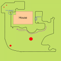
Mowing zones between adjacent surfaces
Mowing zones can be set up between adjacent surfaces that have a direct connection. For this, the perimeter cable between the surfaces is laid at a distance of about 13cm. A gap of about 30cm or less is left to the opposite perimeter cable. This reduces the likelihood that the robot will move to the other area.
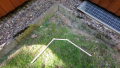
See image:
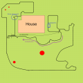
Beispiel, Mähzonenabgrenzung
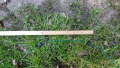
Abmessungen


(In the picture above, it is not normally necessary to set up mowing zones, as the robot covers relatively well all areas of the lawn by the algorithm.)
The distance of the area delineation cable to the opposite perimeter cable (here 30cm distance) can be optimized by tests. The distance depends on the functionality of the perimeter tracking. Firstly, the position of the left coil when tracking the overlying cable, as well as the tracking of the area delineation cable itself.
In config.h the constant CONF_USE_ZONE_RECOGNITION should be set to true.
#define CONF_USE_ZONE_RECOGNITION true
Since the robot travels with the coils about 20 cm over the cable by default, it may be that it stops with the coils within the next range. If CONF_USE_ZONE_RECOGNITION is false, the robot would simply continue driving as it may have crossed a corner. If CONF_USE_ZONE_RECOGNITION is true, it will be checked after crossing if both coils are inside the perimeter again. If so, at least a distance of (-CONF_PERIMETER_DRIVE_BACK_CM-10) is returned. So 10cm more than usual CONF_PERIMETER_DRIVE_BACK_CM would go back.
Approaching an area from the charging station is done with the command:
area,x // where x is the path to be traveled in m.
If the specified distance x has been covered at the perimeter, the Mower starts mowing.
The distance traveled on the perimeter can be displayed or measured with the command.
show.distance
Attention: It is important to remember exactly where the mower zone cables are located in case the grass is scarred..
Laying the Perimeter Cable at Corners
The Mower determines in which direction he turns on the perimter on the basis of the coil that was pulled out first. Therefore it is important not to lay the corners at 90 degrees. For example, if the Mower, with the right spool, moves close parallel to the perimeter and then drives out at the corner, the right spool should also be the first to leave the perimeter.
The following pictures show three examples of how corners should be moved..
Außenecke
Außenecke
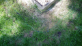
Innenecke


Temperature Sensor
The temperature sensors DHT11 / DHT21 / DHT22 / AM2301 are supported. Currently only the sensor DHT22 was tested. The temperature sensor is connected to the designated port of the PCB1.3.
In config.h the used temperature sensor must be configured:
#define DHTTYPE DHT22
To enable the service, the following line must be configured:
#define CONF_DISABLE_DHT_SERVICE false // Disables temp sensor
The sensor is read out with the following command:
temp.show
In manual mode, the sensor is read out directly. Temperature, humidity and the last temperature stored in the service are displayed. In auto mode, only the temperature stored in the service is displayed. The temperature is updated when the mower drives over the perimeter wire and comes to a stop and time has passed at least 20 seconds since the last measurement.
The DHT service turns off the power of the PCB1.3 when a temperature of 50 degrees has been measured twice:
#define CONF_OVERHEATING_TEMP 50.0f // if this temperature is measured, robot shuts down the complete power for security
Shutdown Service
When the shutdown service is activated, it shuts off the power via the undervoltage protection. If a Raspberry PI is connected to the USB port,
CONF_WAIT_FOR_PI_SHUTDOWN = true
can be set. Then the software waits 50 seconds for shutdown. Every second, $PwrOff and a countdown are sent to the PI so that it can shut down.
With the command: poweroff the shutdown can be activated via the user interface or from the PI.
The shutdown service is also used by the battery service and the temperature service to shut down. Thus, the PI is informed that it should shut down if the battery voltage is too low or the temperature too high.
GPS Service
The GPS service receives the data from the GPS module.
There are two ways to process this data. Both options can be used in parallel.
a) The received GPS data will be forwarded to the Raindancer Controlcenter.
b) The received GPS data are evaluated in the Raindancer firmware. You can then define an area on the lawn.
   If the mower is in this area, it is assumed that the mower is inside the perimeter wire. So it is possible to bridge a weak perimeter signal on larger areas.
The GPS module is connected to the dedicated connector on PCB1.3. The GPS module periodically sends data to PCB1.3. If no data is received, please read the following article. It may be that RX3 and TX3 on the PCB1.3 were wired incorrectly. https://www.ardumower.de/index.php/de/forum/navigation-gps-odmetrie/1737-wait-for-gps-position-data
Send to the Raindancer Controlcenter
To enable the GPS service, the following must be configured::
#define CONF_DISABLE_GPS false
For the first commissioning you can set the following parameters:
#define CONF_GPS_PASS_THROUGH true
#define CONF_DEACTIVATE_GPS_CALCULATION true
The parameter #define CONF_GPS_PASS_THROUGH tells the firmware that all received GPS data should be sent to the control center.
In order to get this data displayed on the console, the following command must be executed:
set.cco, 1
Now you can see all the data sent to the control center. Including the GPS records.
With the following command you stop the output:
set.cco,0
By default, the GPS module sends multiple records in a 1 second interval. These records are not all needed and generate an overhead. Only the record: $GPRMC for NEO-6M and $GNRMC for NEO-M8N are needed. Therefore, there is the possibility to configure the module when starting the Raindancer firmware so that it sends only the required record and this only in a 3 second cycle. For this the following parameter is set:
#define CONF_INIT_GPS_WITH_UBLOX true
Thus the array const char UBLOX_INIT [] (in config.h) is sent to the GPS module during startup. To activate or deactivate you have to comment in or comment out individual lines.
Enable internal calculation
Again #define CONF_INIT_GPS_WITH_UBLOX should be true. To activate the internal calculation CONF_DEACTIVATE_GPS_CALCULATION must be set.
#define CONF_DEACTIVATE_GPS_CALCULATION false
For the NEO-6M module, the record: $GPRMC is used. The NEO-M8N uses the record $GNRMC. Therefore, the following lines must be commented in or out depending on the module used:
#define CONF_N_GPRMC_STR            "$GPRMC"    // GPS messagetype begin for $GPRMC for NEO-6M
//#define CONF_N_GPRMC_STR          "$GNRMC"    // GPS messagetype begin for $GPRMC for NEO-M8N
With
gps.show
you can display the calculated values.
If you have included the "GxGGA on" data set in UBLOX_INIT [], then Quality, Satellites and Altitude will also be displayed. These are not used anymore for other things.
It is possible to configure a GPS area in which the Mower assumes he is in the perimeter if the perimeter signal is too weak for detection.
The area is specified as a polygon.
const float CONF_LAT_POLYGON_Y[] = { 54.083245f, 54.084068f,  54.084679f,  54.085623f,  54.084018f }; // Latitude polygon points
const float CONF_LON_POLYGON_X[] = { 10.447986f, 10.447055f,  10.446015f,  10.447120f,  10.44930f }; // Longitudinal polygon points
const int   CONF_NUMBER_OF_POLYGON_POINTS = 5;  // The number of the ploygon points
Each column belongs to a polygon point. You can at https://www.google.com/maps enter a point in the search: 54.08728,10.448400. Then you can see where this coordinate is. So you can see point by point how the polygon is constructed. It is important that the number of columns is defined correctly with CONF_NUMBER_OF_POLYGON_POINTS. You can enter 3 to N coordinate points. However, I suggest you use no more than 8 points to make the calculation time as low as possible
To find the points, you can set the robot to the appropriate point and enter gps.show. Then, e.g. the following is displayed:
!03,$GPRMC,104503.00,A,5123.24690,N,00812.92063,E,0.094,,290718,,,A*72
!03,$GPRMC speed: 0.094000 course:0.000000
!03,$GPRMC lat: 54.08744800,N lon: 10.44867700,E
!03,$GPRMC date: 29.7.18 time: 11:45:3
The point can then be taken from the line! 03,$GPRMC,lat:53.08744800,N lon:9.44867700,E. Here for Latitude = 54.087448 and Longitude = 10.448677.
The area recognition is switched on with:
#define CONF_USE_GPS_POLYGON true
It should be noted that the GPS signal has a tolerance of +-10m. That you should stay far enough away from the perimeter. Because that does sometimes not work, the parameter
#define CONF_PER_THRESHOLD_IGNORE_GPS 300
was introduced. This means that if the amplitude of the perimeter exceeds this value, the perimeter signal will be used in any case and will not be overwritten by the GPS signal, even if the mower is in the GPS range. The value 300 must be set according to your own requirements..
![]() Safety Note: If the perimeter signal fails and the GPS range exceeds the perimeter, the mower will leave the perimeter area
Safety Note: If the perimeter signal fails and the GPS range exceeds the perimeter, the mower will leave the perimeter area
Perimeter Sender
The original Ardumower transmitter hardware is used. The software has been changed slightly. A 128 bit signal is sent. The following perimeter signal is sent:
1, 1, -1, -1, -1, 1, -1, -1, 1, -1, 1, -1, -1, 1, 1, -1, 1, 1, -1, -1, 1, 1, -1, 1, 1, -1, 1, -1, 1, -1, -1, 1, -1, -1, 1, -1, 1, 1, -1, 1, -1, 1, -1, 1, -1, 1, 1, -1, -1, 1, 1, -1, -1, 1, 1, -1, 1, -1, 1, 1, -1, -1, 1, -1,
-1, 1, 1, -1, 1, 1, -1, -1, 1, -1, -1, 1, -1, 1, -1, 1, 1, -1, 1, -1, -1, 1, -1, -1, 1, 1, -1, 1, -1, -1, 1, 1, -1, 1, -1, 1, -1, 1, -1, 1, -1, 1, 1, -1, -1, 1, -1, -1, 1, -1, 1, -1, -1, 1, -1, -1, 1, 1, -1, 1, 1, -1, -1, 1
The LEDs have the following function (from left to right):
- 1. 12V available
- 2. 5V available
- 3. Green when the interrupt which produces the signal is running (red LED not available because of wrong pin at Nano). Off when charging.
- 4. Green when a current flows through the perimeter, red when no current is flowing (perimeter interrupted) or very little current because of high protective resistor. Off when charging.
- 5. Yellow the robot is charging. Perimeter signal is switched off. LED 2 and 4 off.
When power on, all leds will be tested.
Attention: LEDs 3 and 4 are Duo LEDs. These LEDs have two colors. With LED 3. the red LED is not addressable, because on the Nano the wrong pin was hardware-technically connected. Furthermore, the LEDs may have been soldered the wrong way round. Then one wonders, for example, that LED 4 is red even though everything is OK and a current flows. Or just LED 3. shows red, although I have written green here.
If the transmitter is on and the robot does not return to the charging station after twelve hours, the transmitter will turn off the signal. Then either reboot the transmitter or load the robot into the charging station.
Charging Station
The charging stations are approached counterclockwise.
If no charging station is used, CONF_DISABLE_CHARGINGSTATION = true should be set. Then the Mower drives at low battery voltage to the perimeter and stops.
Head charging station
If a head charging station is used, make sure that the contacts can go back at least 3 cm when the Mower drives against it. It would be better 4 cm. Furthermore, it should be noted that the contact pressure of the contact is sufficient.
In order to use a head charging station, the following must be configured in config.h:
#define CONF_DISABLE_CHARGINGSTATION       false
#define CONF_PASS_THROUGH_CHARGING_STATION false //the mower can go through the station
#define CONF_HEAD_CHARGING_STATION         true  //the mower can't go through the station
With the command
go home
the mower is instructed to search the perimeter wire and drive to the charging station.
For testing, the Mower can be placed on the perimeter wire, 2m in front of the charging station. Then enter
tpt
The Mower then drives to the charging station.
To leave the charging station enter
area, 0
The Mower then drives 1m backwards, turns 90 degrees and drives 50cm forward. Then turn again a random angle and starts to mow. This process runs without bumper protection. Therefore, make sure that this area is free of obstacles.
The distances can be configured with the following parameters:
#define CONF_HEAD_CHARGING_DRIVE_BACK_CM   100   //when the mower leaving the head charging station, how far it should drive back
#define CONF_HEAD_CHARGING_DRIVE_FORW_CM    50   //when the mower drove back and then rotates 90 degree, how far it should run forward that both coils securely inside
When the Mower has detected the charging contacts, it will travel 3cm back and 3cm forward.
Then the charge relay is turned on. After 10 seconds, it is checked whether a charging current is flowing. If not, docking will be attempted a second time. If this does not work, an error will be issued.
Through Charging Station
If a through charging station is used, make sure that the contacts can grind at least 10cm. Furthermore, it should be noted that the contact pressure of the contact is sufficient.
In order to use a through charging station, the following must be configured in config.h:
#define CONF_DISABLE_CHARGINGSTATION       false
#define CONF_PASS_THROUGH_CHARGING_STATION true   //the mower can go through the station
#define CONF_HEAD_CHARGING_STATION         false  //the mower can't go through the station
With the command
go home
the mower is instructed to search the perimeter wire and drive to the charging station.
For testing, the Mower can be placed on the perimeter wire, 2m in front of the charging station. Then enter
tpt
The Mower then drives to the charging station.
To leave the charging station enter area, 10 The Mower then travels 10m along the perimeter wire and then starts mowing. 10m can be exchanged against any distance.
When the Mower has detected the charging contacts, it will move forward 4cm, back 3cm and forward 3cm. This is to make the contacts to grind a little for better contact.
Then the charger relay is turned on. After 10 seconds, it is checked whether a charging current is flowing. If not, docking will be attempted a second time. If this does not work, an error will be output.
Troubleshooting
Mower stops
Problem: Mower stopped, cause was probably the transmitter. On the transmitter just lights still the two left LEDs. Transmitter turned and on again, 4 LEDs back to green and then it works again.
Solution: The third green light from the left indicates whether the transmitter Interrupt is running in the Nano.
Possibility A) The transmitter is on for more than 12 hours without the robot returning to the station. Then the transmitter turns off the perimeter signal.
Possibility b) Since this was not on, the nano seems to have hung up. If that happens again, I would swap the China Nano for an original Arduino Nano. Since the software has been running for me for a year, I do not assume that the software is the cause. I had used cheap nanos before. They were not really frequency stable with me, which is necessary for the transmitter however. Now I have an original in it.
I got the message: Out: READ und In: CMD
Problem: In Arduino Central wird folgendes angezeigt:
Out: READ
In: CMD: Command not recognized.
Out: READ
In: CMD: Command not recognized.
Out: READ
In: CMD: Command not recognized.
Out: READ
Suggested solution: In the Arduino Central Settings "Read Command -> Enable Read Command" is activated
Understanding the Behaviour Tree
- REDIRECT Understanding the Behaviour Tree