WIFI Perimeter Sender(English)
WIFI Perimeter sender.
Inhaltsverzeichnis
WIFI PERIMETER SENDER
It's ESP32 base sender that you can start and stop from your WIFI,it's only wired version,so don't really need PCB.
If you want a PCB for less wire you can find one in the GITHUB pag with the 3D file for box.
https://github.com/Boilevin/AzuritBer/tree/master/Sender%20WIFI


Button is not use.
Hardware
You need :
1 ESP32 DEV KIT V1 (or later but with same pin diagram).


1 INA3221 3-Channel DC Current Sensor :

1 I2C Small OLED Display https://www.marotronics.de/Ecran-OLED-13-blanc-SH1106-128x64-I2C-module-Arduino-Raspberry-Pi

1 DC/DC Converter https://www.marotronics.de/Module-abaisseur-5A-DC-DC-XL4015-avec-dissipateur-thermique-par-exemple-pour-Arduino

1 L298N motor Driver. https://www.marotronics.de/Driver-de-moteur-L298N-Dual-H-Bridge-Motor-Driver

1 power Supply. https://www.marotronics.de/Chargeurs-pour-batteries-Ardumower-24V-avec-LED-detat-egalement-pour-batteries-Li-Ion
If it's charging station you need the correct charger
If area 2 or 3 it's possible to use a 12V one

1 Power Resistor.

Perimeter wire. https://www.marotronics.de/Boucle-de-recherche-de-cable-peripherique-de-100-m-27mm-pour-Ardumower-Husqvarna-Automower-Gardena-Indego

WIRING
Now you need to connect everything together.
Option 1
It's the same that standard sender Only one perimeter wire is used.

Option 2
2 area perimeter wire are possible to use 2 mowing area

Option 3
1 area perimeter wire and 1 DC motor for a door. Be careful that the code is not actually write for this feature.

PROGRAMMING ESP32
Use code locate into github: https://github.com/Boilevin/AzuritBer/tree/master/Sender%20WIFI
Select sender_ESP32_INA3221_2loops (it's the 2 loops version and work also on 1 loop)
Now check the 40 first line of code and adjust according your need.
If your home WIFI is OK at the sender location ,you need to use your home SSID and password value.
If the sender don't have access to your home WIFI ,you need to use raspberry PI as access point and use the pi SSID and password.
ssid     = "your acces point ssid";   // put here your acces point ssid
password = "password";  // put here the password
Now put a static IP (the last number need to be unique on your network and different for each sender) On Piardu config.py you need to set the correct IP according sender (Sender1AdressIP="10.0.0.150",Sender2AdressIP="10.0.0.151",sender3AdressIP="10.0.0.154") if you want that mower can start and stop sender 2 or 3 over WIFI.
If you use the 2 loops ,you need to connect the station perimeter wire (AREA1) to signal A and the AREA2 to signal B on the L298N driver.
If it's a simple sender for area2 or area3 without charging station use the signal B on L298N driver
staticIP(10, 0, 0, 154); // put here the static IP
gateway(10, 0, 0, 1); // put here the gateway (IP of your routeur)
Now you can set the last value:
DcDcOutVoltage set it according your DC/DC voltage regulator output (MAX 12V)
USE_STATION set to 0 if it's area2 or area3 without charging station or 1 if it's the main area
USE_PERI_CURRENT set it to 1 if you want to detect when perimeter wire is cut
PERI_CURRENT_MIN it's the min value to detect that wire is cut
USE_BUTTON set to 0 because not use actually
USE_RAINFLOW set to 0 because not use actually
WORKING_TIMEOUT_MINS when robot is not in station signal is send for this max duration.
#define USE_STATION     0 // a station is connected and is used to charge the mower
#define USE_PERI_CURRENT      1     // use Feedback for perimeter current measurements? (set to '0' if not connected!)
#define USE_BUTTON      1     // use button to start mowing or send mower to station not finish to dev
#define USE_RAINFLOW    0     // check the amount of rain not finish to dev on 31/08/2020
#define WORKING_TIMEOUT_MINS 300  // timeout for perimeter switch-off if robot not in station (minutes)
#define PERI_CURRENT_MIN    100    // minimum milliAmpere for cutting wire detection
You need to use Arduino IDE to upload code into ESP32, It's easy and exactly same process that for Arduino DUE or Mega ,but need to select the correct board.
Add the ESP32 board to your arduino IDE: for more info see : https://github.com/espressif/arduino-esp32/blob/master/docs/arduino-ide/boards_manager.md
Open your Arduino Ide 1.8 or later
Select ESP32 DEV Module and correct COM port


To upload code do not forget : At the end of compilation when you see "connecting ....." --> push the BOOT button locate on ESP32 DEV KIT for 5 sec to start uploading


TESTING
 BEFORE CONNECTING TO CHARGER ADJUST THE DC/DC CONVERTER OUT TO 9V or more BUT MAXIMUM 12V
Test the total resistor of your perimeter wire and add the power resistor according U=R*I for a maximum of 1 Ampere on the loop.
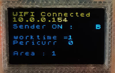
Plug power supply and check Oled display .
You need to see the welcome message with version number and sender start to scan your WIFI until find the SSID that you have set in the firmware.

If everything is OK you can see the connected message with IP adress.
On startup and if it's not station sender signal is OFF,if it's station one and mower is not into station signal is ON until mower back to station.

You can use your PC,tablet,or phone and enter into navigator some command to check if everything is OK:
10.0.0.154/A1 to start sender on output A of the L298N


10.0.0.154/B1 to start sender on output B of the L298N

10.0.0.154/A0 to stop sender on output A of the L298N

10.0.0.154/? to see the state of sender

Using AZURITBER and level3 the sender area2 and 3 start and stop automatically when mower need it.