Ardumower Mini: Unterschied zwischen den Versionen
(→Steps) |
(→Steps) |
||
| Zeile 23: | Zeile 23: | ||
The Ardumower Mini can run the same software as the 'big Ardumower'. For the PCB, you don't need to use a Ardumower PCB - instead you can (with some limitation) connect the components directly as shown below. The limitations are: there will be no battery charging circuit, and of course your wiring will not look as nice as a ready PCB :-) | The Ardumower Mini can run the same software as the 'big Ardumower'. For the PCB, you don't need to use a Ardumower PCB - instead you can (with some limitation) connect the components directly as shown below. The limitations are: there will be no battery charging circuit, and of course your wiring will not look as nice as a ready PCB :-) | ||
| − | For software download, see the [ | + | |
| + | For software download, see the [http://wiki.ardumower.de/index.php?title=Ardumower_PCB Ardumower PCB/code page]. In the Arduino IDE, go into file 'config.h', and activate the pin configuration for the Ardumower Mini (enable '#define USE_MINI' and disable '#define USER_MOWER'). Now the code will use the Ardumower Mini pin configuration file ('mini.cpp'). | ||
| + | |||
NOTE: Do not use more than 7 volt to operate the DC motors! | NOTE: Do not use more than 7 volt to operate the DC motors! | ||
1. Start button | 1. Start button | ||
| − | Button (a) --- Arduino pinButton (see code) | + | Button (a) --- Arduino pinButton (see code: mini.cpp) |
Button (b) --- GND | Button (b) --- GND | ||
2. Piezo buzzer | 2. Piezo buzzer | ||
| − | Buzzer (a) --- Arduino pinBuzzer (see code) | + | Buzzer (a) --- Arduino pinBuzzer (see code: mini.cpp) |
Buzzer (b) --- GND | Buzzer (b) --- GND | ||
| Zeile 43: | Zeile 45: | ||
GND --- LiPo 2s battery 7volt (-) | GND --- LiPo 2s battery 7volt (-) | ||
ENA --- insert jumper (enables OUT1,2) | ENA --- insert jumper (enables OUT1,2) | ||
| − | IN1 --- Arduino pinMotorLeftPWM (see code) | + | IN1 --- Arduino pinMotorLeftPWM (see code: mini.cpp) |
| − | IN2 --- Arduino pinMotorLeftDir (see code) | + | IN2 --- Arduino pinMotorLeftDir (see code: mini.cpp) |
| − | IN3 --- Arduino pinMotorRightPWM (see code) | + | IN3 --- Arduino pinMotorRightPWM (see code: mini.cpp) |
| − | IN4 --- Arduino pinMotorRightDir (see code) | + | IN4 --- Arduino pinMotorRightDir (see code: mini.cpp) |
ENB --- insert jumper (enables OUT3,4) | ENB --- insert jumper (enables OUT3,4) | ||
S1 --- insert jumper (enables 5v regulator for +12v voltage input) | S1 --- insert jumper (enables 5v regulator for +12v voltage input) | ||
| Zeile 56: | Zeile 58: | ||
3.2 For MC33926 motor driver | 3.2 For MC33926 motor driver | ||
| − | M1_FB --- Arduino pinMotorLeftSense (see code) | + | M1_FB --- Arduino pinMotorLeftSense (see code: mini.cpp) |
| − | M1_SF --- Arduino pinMotorLeftFault (see code) | + | M1_SF --- Arduino pinMotorLeftFault (see code: mini.cpp) |
M1_PWM_D1 --- connect with jumper to GND | M1_PWM_D1 --- connect with jumper to GND | ||
M1_PWM_D2 --- connect with jumper to VDD | M1_PWM_D2 --- connect with jumper to VDD | ||
| − | M1_IN1 --- Arduino pinMotorLeftPWM (see code) | + | M1_IN1 --- Arduino pinMotorLeftPWM (see code: mini.cpp) |
| − | M1_IN2 --- Arduino pinMotorLeftDir (see code) | + | M1_IN2 --- Arduino pinMotorLeftDir (see code: mini.cpp) |
| − | EN --- Arduino pinMotorEnable (see code) | + | EN --- Arduino pinMotorEnable (see code: mini.cpp) |
| − | M2_FB --- Arduino pinMotorRightSense (see code) | + | M2_FB --- Arduino pinMotorRightSense (see code: mini.cpp) |
| − | M2_SF --- Arduino pinMotorRightFault (see code) | + | M2_SF --- Arduino pinMotorRightFault (see code: mini.cpp) |
M2_PWM_D1 --- connect with jumper to GND | M2_PWM_D1 --- connect with jumper to GND | ||
M2_PWM_D2 --- connect with jumper to VDD | M2_PWM_D2 --- connect with jumper to VDD | ||
| − | M2_IN1 --- Arduino pinMotorRightPWM (see code) | + | M2_IN1 --- Arduino pinMotorRightPWM (see code: mini.cpp) |
| − | M2_IN2 --- Arduino pinMotorRightDir (see code) | + | M2_IN2 --- Arduino pinMotorRightDir (see code: mini.cpp) |
| − | EN --- Arduino pinMotorEnable (see code) | + | EN --- Arduino pinMotorEnable (see code: mini.cpp) |
VDD --- Arduino 5V | VDD --- Arduino 5V | ||
M1OUT1 --- left motor (+) | M1OUT1 --- left motor (+) | ||
| Zeile 80: | Zeile 82: | ||
4. Arduino Mega | 4. Arduino Mega | ||
Power jack --- LiPo 2s battery 7volt (outside is-/inside is+) | Power jack --- LiPo 2s battery 7volt (outside is-/inside is+) | ||
| − | pinMotorLeftPWM --- left motor speed (see code | + | pinMotorLeftPWM --- left motor speed (see code : mini.cpp) |
| − | pinMotorLeftDir --- left motor direction (see code) | + | pinMotorLeftDir --- left motor direction (see code: mini.cpp) |
| − | pinMotorRightPWM --- right motor speed (see code) | + | pinMotorRightPWM --- right motor speed (see code: mini.cpp) |
| − | pinMotorRightDir --- right motor direction (see code) | + | pinMotorRightDir --- right motor direction (see code: mini.cpp) |
5. Bluetooth receiver | 5. Bluetooth receiver | ||
| Zeile 94: | Zeile 96: | ||
6. Sonar (ultrasonic) | 6. Sonar (ultrasonic) | ||
VCC --- Arduino 5v | VCC --- Arduino 5v | ||
| − | Trig --- Arduino pinSonarCenterTrigger (see code) | + | Trig --- Arduino pinSonarCenterTrigger (see code: mini.cpp) |
| − | Echo --- Arduino pinSonarCenterEcho (see code) | + | Echo --- Arduino pinSonarCenterEcho (see code: mini.cpp) |
GND --- Arduino GND | GND --- Arduino GND | ||
7. Model R/C | 7. Model R/C | ||
VCC --- Arduino 5v | VCC --- Arduino 5v | ||
| − | CHANNEL steer --- Arduino pinRemoteSteer (see code) | + | CHANNEL steer --- Arduino pinRemoteSteer (see code: mini.cpp) |
| − | CHANNEL speed --- Arduino pinRemoteSpeed (see code) | + | CHANNEL speed --- Arduino pinRemoteSpeed (see code: mini.cpp) |
8. IMU (compass/gyro/accel) | 8. IMU (compass/gyro/accel) | ||
| Zeile 114: | Zeile 116: | ||
GND --- coil (b) | GND --- coil (b) | ||
GND --- Arduino GND | GND --- Arduino GND | ||
| − | Out --- Arduino pinPerimeterLeft (see code) | + | Out --- Arduino pinPerimeterLeft (see code: mini.cpp) |
Version vom 14. Mai 2015, 20:16 Uhr
Inhaltsverzeichnis
Abstract
This page describes the 'Ardumower Mini' that can be used to implement a full Ardumower for indoor software development and
that you can purchase via the shop ![]()
Needed parts
Pictures
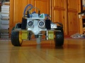
Ardumower mini front
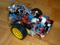
Ardumower mini side
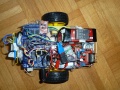
Ardumower mini top
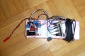
Indoor perimeter sender (L298-based)


Videos
Steps
The Ardumower Mini can run the same software as the 'big Ardumower'. For the PCB, you don't need to use a Ardumower PCB - instead you can (with some limitation) connect the components directly as shown below. The limitations are: there will be no battery charging circuit, and of course your wiring will not look as nice as a ready PCB :-)
For software download, see the Ardumower PCB/code page. In the Arduino IDE, go into file 'config.h', and activate the pin configuration for the Ardumower Mini (enable '#define USE_MINI' and disable '#define USER_MOWER'). Now the code will use the Ardumower Mini pin configuration file ('mini.cpp').
NOTE: Do not use more than 7 volt to operate the DC motors!
1. Start button
Button (a) --- Arduino pinButton (see code: mini.cpp)
Button (b) --- GND
2. Piezo buzzer
Buzzer (a) --- Arduino pinBuzzer (see code: mini.cpp)
Buzzer (b) --- GND
3. Motor driver
3.1 For L298N motor driver
+5v  --- leave open
+12v --- LiPo 2s battery 7volt (+)
GND  --- LiPo 2s battery 7volt (-)
ENA  --- insert jumper (enables OUT1,2)
IN1  --- Arduino pinMotorLeftPWM  (see code: mini.cpp)
IN2  --- Arduino pinMotorLeftDir  (see code: mini.cpp)
IN3  --- Arduino pinMotorRightPWM (see code: mini.cpp)
IN4  --- Arduino pinMotorRightDir (see code: mini.cpp)
ENB  --- insert jumper (enables OUT3,4)
S1   --- insert jumper (enables 5v regulator for +12v voltage input)
OUT1 --- left motor (+)
OUT2 --- left motor (-)
OUT3 --- right motor (+)
OUT4 --- right motor (-)
3.2 For MC33926 motor driver
M1_FB     --- Arduino pinMotorLeftSense (see code: mini.cpp)
M1_SF     --- Arduino pinMotorLeftFault (see code: mini.cpp)
M1_PWM_D1 --- connect with jumper to GND
M1_PWM_D2 --- connect with jumper to VDD
M1_IN1    --- Arduino pinMotorLeftPWM (see code: mini.cpp)
M1_IN2    --- Arduino pinMotorLeftDir (see code: mini.cpp)
EN        --- Arduino pinMotorEnable  (see code: mini.cpp)
M2_FB     --- Arduino pinMotorRightSense (see code: mini.cpp)
M2_SF     --- Arduino pinMotorRightFault (see code: mini.cpp)
M2_PWM_D1 --- connect with jumper to GND
M2_PWM_D2 --- connect with jumper to VDD
M2_IN1    --- Arduino pinMotorRightPWM (see code: mini.cpp)
M2_IN2    --- Arduino pinMotorRightDir (see code: mini.cpp)
EN        --- Arduino pinMotorEnable (see code: mini.cpp)
VDD       --- Arduino 5V
M1OUT1    --- left motor (+)
M1OUT2    --- left motor (-)
M2OUT1    --- right motor (+)
M2OUT2    --- right motor (-)
VIN       --- LiPo 2s battery 7volt (+)
GND       --- LiPo 2s battery 7volt (-)
4. Arduino Mega
Power jack       ---  LiPo 2s battery 7volt (outside is-/inside is+)
pinMotorLeftPWM  ---  left motor speed (see code : mini.cpp)
pinMotorLeftDir  ---  left motor direction (see code: mini.cpp)
pinMotorRightPWM ---  right motor speed (see code: mini.cpp)
pinMotorRightDir ---  right motor direction (see code: mini.cpp)
5. Bluetooth receiver
VCC5.0  --- Arduino 5v   (for 5v Bluetooth version)
VCC3.3  --- Arduino 3.3v (for 3.3v Bluetooth version)
TXD     --- Arduino RX2
RXD     --- Arduino TX2
GND     --- Arduino GND
6. Sonar (ultrasonic)
VCC     --- Arduino 5v
Trig    --- Arduino pinSonarCenterTrigger (see code: mini.cpp)
Echo    --- Arduino pinSonarCenterEcho (see code: mini.cpp)
GND     --- Arduino GND
7. Model R/C
VCC           --- Arduino 5v
CHANNEL steer --- Arduino pinRemoteSteer (see code: mini.cpp)
CHANNEL speed --- Arduino pinRemoteSpeed (see code: mini.cpp)
8. IMU (compass/gyro/accel)
SDA     --- Arduino SDA
SCL     --- Arduino SCL
GND     --- Arduino GND
VCC5.0  --- Arduino 5v
9. Perimeter receiver
VCC     --- Arduino 5v
IN      --- coil (a)
GND     --- coil (b)
GND     --- Arduino GND
Out     --- Arduino pinPerimeterLeft (see code: mini.cpp)