Ardumower Sunray: Unterschied zwischen den Versionen
Aus www.wiki.ardumower.de
(→Compass calibration) |
(→Compass calibration) |
||
| Zeile 12: | Zeile 12: | ||
# Move IMU out of robot and power-on robot. | # Move IMU out of robot and power-on robot. | ||
# Start 'processing_mag'. | # Start 'processing_mag'. | ||
| − | [[File:Compass_calibration.png| | + | [[File:Compass_calibration.png|600px]] |
# Ensure there is at least >1m to all metal parts in the surrouding. | # Ensure there is at least >1m to all metal parts in the surrouding. | ||
# Rotate IMU module slowly into all directions and collect > 20,000 measurements. | # Rotate IMU module slowly into all directions and collect > 20,000 measurements. | ||
Version vom 29. April 2017, 15:42 Uhr
Requirements
- PCB 1.3 (incl. MC33926 motor drivers)
- Arduino Due
- IMU GY-88 (MPU6050, HMC5883L)
- 2 perimeter coils (left, right), perimeter sender
- motors using odometry
- Bluetooth module
Compass calibration
- Install IMU module 35cm away from metal parts. Use 1m cable so you can move the module out of robot for calibration.
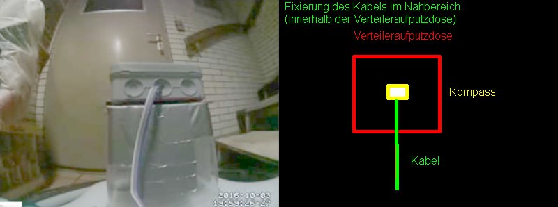 . Do no use metal parts (screws etc.) within 5cm of the module, use plastic screws. Fixate everything within 5cm of the module. A small movement of a cable etc. will make the calibration useless.

- Move IMU out of robot and power-on robot.
- Start 'processing_mag'.


- Ensure there is at least >1m to all metal parts in the surrouding.
- Rotate IMU module slowly into all directions and collect > 20,000 measurements.
- Install IMU module in robot at least 35cm away from metal parts.