Ardumower Sunray: Unterschied zwischen den Versionen
Aus www.wiki.ardumower.de
(→Requirements) |
(→Compass calibration) |
||
| Zeile 10: | Zeile 10: | ||
=Compass calibration= | =Compass calibration= | ||
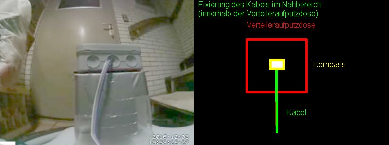
| − | # Install IMU module 35cm away from metal parts. Use 1m cable so you can move the module out of robot for calibration. Do no use metal parts (screws etc.) within 5cm of the module | + | # Install IMU module 35cm away from metal parts. Use 1m cable so you can move the module out of robot for calibration. Do no use metal parts (screws etc.) within 5cm of the module - use plastic screws. Fixate everything within 5cm of the module. A small movement of a cable etc. will make the calibration useless. [[File:Verteileraufputzdose_2017-01-22.jpg]] |
# Move IMU out of robot and power-on robot. | # Move IMU out of robot and power-on robot. | ||
# On the PC, start 'processing_mag'. [[File:Compass_calibration.png|600px]] | # On the PC, start 'processing_mag'. [[File:Compass_calibration.png|600px]] | ||
Version vom 29. April 2017, 15:55 Uhr
Inhaltsverzeichnis
Requirements
- PCB 1.3 (incl. MC33926 motor drivers)
- Arduino Due
- IMU GY-88 (MPU6050, HMC5883L)
- 2 perimeter coils (left, right), perimeter sender
- motors using odometry
- Bluetooth module
Code
https://github.com/Ardumower/Sunray
Compass calibration
- Install IMU module 35cm away from metal parts. Use 1m cable so you can move the module out of robot for calibration. Do no use metal parts (screws etc.) within 5cm of the module - use plastic screws. Fixate everything within 5cm of the module. A small movement of a cable etc. will make the calibration useless.
- Move IMU out of robot and power-on robot.
- On the PC, start 'processing_mag'.

- Ensure there is at least >1m to all metal parts in the surrouding.
- Rotate IMU module slowly into all directions and collect > 20,000 measurements. Calibration ist performed transmitted continously to robot (robot confirms with a tone).
- Install IMU module in the robot at least 35cm away from metal parts.


User interface (for testing/development)
- On the PC, start 'processing_sunray'. The robot's sensors should be shown. At start (and every 3 minutes), the robot calibrates the Gyro and calibration status is shown in the user interface. After this is completed, you can verify the compass calibration by rotating the robot using the green joystick shown on the screen. Compass yaw and gyro yaw should be same up to 3 degree.
