Ardumower Sunray: Unterschied zwischen den Versionen
(→Code) |
(→Compass calibration) |
||
| Zeile 36: | Zeile 36: | ||
=Compass calibration= | =Compass calibration= | ||
| + | Ardumower Sunray relies on a carefully-performed compass calibration, so it knows the robot's direction up to 3 degrees. | ||
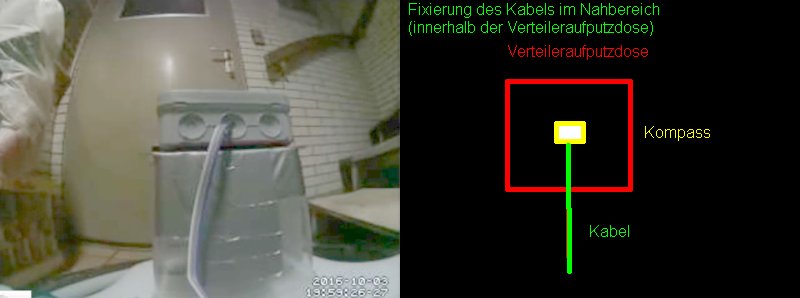
# Install IMU module 35cm away from metal parts. Use 1m cable so you can move the module out of robot for calibration. Do no use metal parts (screws etc.) within 5cm of the module - use plastic screws. Fixate everything within 5cm of the module. A small movement of a cable etc. will make the calibration useless. [[File:Verteileraufputzdose_2017-01-22.jpg]] | # Install IMU module 35cm away from metal parts. Use 1m cable so you can move the module out of robot for calibration. Do no use metal parts (screws etc.) within 5cm of the module - use plastic screws. Fixate everything within 5cm of the module. A small movement of a cable etc. will make the calibration useless. [[File:Verteileraufputzdose_2017-01-22.jpg]] | ||
# Move IMU out of robot and power-on robot. | # Move IMU out of robot and power-on robot. | ||
Version vom 29. April 2017, 17:08 Uhr
Inhaltsverzeichnis
NOTE: everything here is still in development! Use Azurit firmware instead if you need a working firmware...
Ardumower Sunray is the next Firmware (experimental) for the Ardumower. It uses odometry, an IMU (gyro+compass) and a perimeter to localize itself on the perimeter and within the perimeter. A particle filter estimates the robot position on a map based on moved distance and absolute angle.
Demo video: https://www.youtube.com/watch?v=Ewqkd6leQjc
Requirements
- Ardumower PCB 1.3 (incl. MC33926 motor drivers) - for PCB1.2 see further below
- Arduino Due
- IMU GY-88 (MPU6050, HMC5883L) installed on a 'tower'
- 2 perimeter coils (left, right), Ardumower perimeter sender
- Ardumower motors using odometry
- Bluetooth module and PC using USB Bluetooth dongle (e.g. Delock EDR 150m)

PCB1.2
Arduino Due operates at 3.3v - PCB1.2 is not designed to work for 3.3v, however you can modify and use PCB1.2 (with limitations/on your own risk):
- Remove Jumper JP3 (PowerA3.3) and Jumper JP12 (PowerA5.0) so no Arduino voltage regulators are used. Remove any measurement jumpers as well (Mess3.3 etc.).
- Set DC-DC U7 to 3.3v (all old 5v lines and VCC-lines on the PCB will now operate at 3.3v !)
- Set DC-DC U6 to 5.0v (all old 3.3v lines on the PCB will now operate at 5.0v ! It's recommended to make big labels on the PCB so you get not confused later!).
- MC33926 motor driver and INA169 module and odometry will now operate at 3.3v. Change VCC pin for the following modules to operate them at 5v:
- HC-05 module operates at 5v
- GY88 module (IMU) operates at 5v (SCL, SDA lines operate at 3.3v).
- LM386 modules (perimeter) operate at 5v.
Code
- Using Arduino IDE, flash the Sunray firmware onto your Arduino Due: https://github.com/Ardumower/Sunray
- Using 'processing_sunray', verify that the bluetooth connection to the Firmware is working.
Bluetooth connection
Choose COM port for your Bluetooth connection. In processing_sunray.pde:
String comPort = "COM9";
Compass calibration
Ardumower Sunray relies on a carefully-performed compass calibration, so it knows the robot's direction up to 3 degrees.
- Install IMU module 35cm away from metal parts. Use 1m cable so you can move the module out of robot for calibration. Do no use metal parts (screws etc.) within 5cm of the module - use plastic screws. Fixate everything within 5cm of the module. A small movement of a cable etc. will make the calibration useless.
- Move IMU out of robot and power-on robot.
- On the PC, start 'processing_mag'.
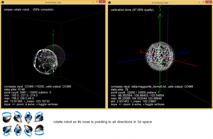
- Ensure there is at least >1m to all metal parts in the surrouding.
- Rotate IMU module slowly into all directions and collect > 20,000 measurements. Calibration ist performed transmitted continously to robot (robot confirms with a tone).
- Install IMU module in the robot at least 35cm away from metal parts.


User interface (for testing/development)
- On the PC, start 'processing_sunray'. The robot's sensors should be shown. At start (and every 3 minutes), the robot calibrates the Gyro and calibration status is shown in the user interface. After this is completed, you can verify the compass calibration by rotating the robot using the green joystick shown on the screen. Compass yaw and gyro yaw should be the same up to 3 degree.

Recording / Playback
You can record or playback all robot messages (e.g. to test the particle filter offline). In processing_sunray.pde:
String logFile = "outdoor_mow_rand.log"; // if file exists, playback mode, otherwise record mode
Mapping
Before you can localize the robot on the map, it needs to be generated.
- On the PC start 'processing_sunray' and connect to robot via Bluetooth.
- Put robot on perimeter, as close as possible to charging station (for anti-clockwise tracking).
- On the PC, choose 'track anti-clockwise' and 'mapping is ON'.
- Let robot track perimeter until it returns at the other side of charging station.
- Press 'mapping is OFF'. The map will be generated and stored on the PC.
Localization
A particle filter will estimate the robot's position on the map. You can reset the particle filter at any time by clicking 'reset particles'. In tracking mode, slightly different particle filter parameters will be used than during ordinary mowing. You can set the robot's position manually (kidnap robot) by clicking on the map.
Random mowing
- On the PC, choose 'mow rand'
Demo video: https://www.youtube.com/watch?v=tZMAjvR4nxU
Lane-by-lane mowing
- On the PC, choose 'mow lane'
Demo video: https://www.youtube.com/watch?v=T0yondeM3fY
Perimeter tracking
The particle filter will estimate the robot's position on the perimeter while tracking.
- On the PC, choose 'track'
Demo video: https://www.youtube.com/watch?v=rNuw9vNcYpM