Ardumower Sunray: Unterschied zwischen den Versionen
(→RTK GPS test (invalid, float, fix)) |
(→RTK base) |
||
| Zeile 86: | Zeile 86: | ||
2. Connect Xbee LongRange dipole antenna | 2. Connect Xbee LongRange dipole antenna | ||
| − | 3. Connect GPS multifrequency patch antenna | + | 3. Connect GPS multifrequency patch antenna. NOTE: antenna cable is very sensitive, never bend the antenna cable! |
4. Connect a '''USB 5v power supply''' to the USB port marked as ''''POWER+GPS'''' | 4. Connect a '''USB 5v power supply''' to the USB port marked as ''''POWER+GPS'''' | ||
Version vom 17. Februar 2020, 22:31 Uhr
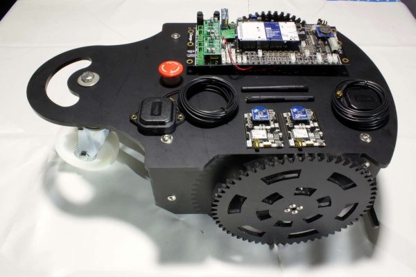
'Mows like on rails...' This is an RTK GPS-based mower that you can build yourself. Ardumower RTK doesn't need a perimeter wire as it uses (cm-precise) RTK GPS.
This page describes how to build your own RTK-GPS mower. It requires an Ardumower DIY robotic mower system and a RTK-GPS kit. You can get the RTK mower as a whole kit in the shop too (click here to get the RTK mower or just the RTK kit).
Inhaltsverzeichnis
- 1 Videos (Demos/Tutorials)
- 2 What is RTK and what are the requirements (environment and hardware)
- 3 Assembling the chassis and PCB
- 4 Significant changes compared to Ardumower's initial firmware (Sunray vs. Azurit)
- 5 Installation steps
- 6 Bluetooth BLE UART module
- 7 PCB1.3 GPS pin fix
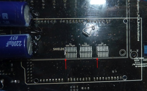
- 8 PCB1.3 odometry divider
- 9 RTK base
- 10 RTK rover
- 11 Rover configuration (messages)
- 12 Download, Arduino Code, Firmware
- 13 Phone App
- 14 Odometry test
- 15 RTK GPS test (invalid, float, fix)
- 16 Discussion / questions / forum thread
- 17 How the waypoints are generated
Videos (Demos/Tutorials)
 Click below to watch demo and tutorial videos:
- Demo: Path planning and mowing demo video
- Demo: Docking demo video (showing cm-precise RTK)
- Tutorial: How to use the app video (German with English subtitles)
What is RTK and what are the requirements (environment and hardware)
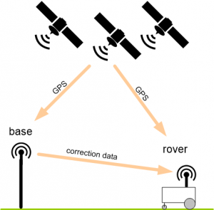
RTK-GPS uses two GPS receivers, one for the reference antenna (base) and one for the robot mower (rover) which both communicate in realtime via radio modules. The base constantly sends correction data so the rover can compute its cm-precise (relative) position. In the RTK-GPS kit, everything required (receivers, radios, antennas etc.) is included.
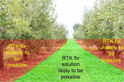
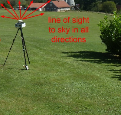
To be able to use RTK-GPS, your robot mower should have a good view to the sky at all locations (see photo below). RTK-GPS will NOT work directly near walls, directly near or under trees, in buildings etc.
These are the hardware requirements to add RTK-GPS to your Ardumower:
- Ardumower chassis kit using Ardumower motors (incl. odometry) and PCB 1.3 (incl. Arduino Due and MC33926 motor drivers)
- RTK kit (it's recommended to purchase the RTK-GPS modules via Marotronics as you get them pre-configured for the Ardumower there)
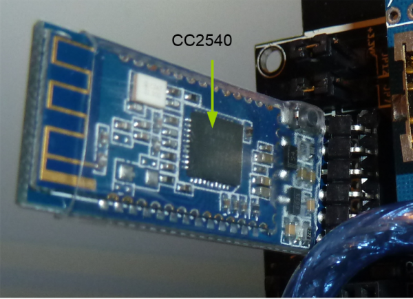
- Bluetooth 4.0/BLE UART module (CC2540)
- A smartphone (Android/iOS) for configuration of your Ardumower
Assembling the chassis and PCB
Please follow the steps described at the main page for assembling chassis, motors etc. and PCB1.3. After you have assembled the chassis and PCB you can follow the steps below for the RTK functionality.
Significant changes compared to Ardumower's initial firmware (Sunray vs. Azurit)
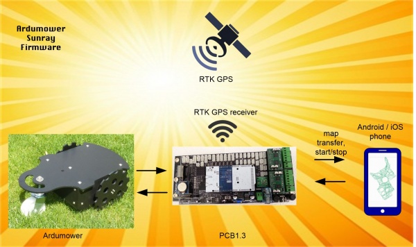
Ardumower Sunray is an alternative Firmware (experimental) for the Ardumower DIY robotic mower system. It uses RTK GPS to localize cm-precise without a perimeter wire. It requires Ardumower PCB1.3, Arduino Due, Ardumower RTK kit, Bluetooth BLE and a phone (Android/iOS).
- Optimized for PCB 1.3
- Optimized for Arduino Due
- Optimized for RTK
-
 Incomplete (Sunray is 'work in progress') - features like docking, GPS signal-loss detection, obstacle detection and avoidance are going to be added soon.
 -
 Experimental (never run your Ardumower unattended with this firmware)
![]() WARNING: everything here is already working but in early prototype phase (never run your Ardumower unattended with this firmware)!
WARNING: everything here is already working but in early prototype phase (never run your Ardumower unattended with this firmware)! ![]()
Use Azurit Firmware instead if you need a firmware with more complete features for your Ardumower...
Installation steps
Bluetooth BLE UART module
1. Install Bluetooth 4.0/BLE module on your Ardumower PCB1.3 (replace any installed Bluetooth 2.0 module).
IMPORTANT: Verify the pinout of your BLE module is matching your Ardumower PCB pinout (shown at the PCB1.3 back side)!
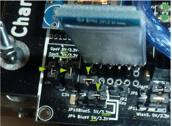
2. Set JP10 (Bluetooth signal level) to 3.3V
3. Set JP4 (Bluetooth voltage) to 5V
4. Set JP7 (GPS voltage) to 5V
5. Set JP12 (GPS signal level) to 5V
PCB1.3 GPS pin fix
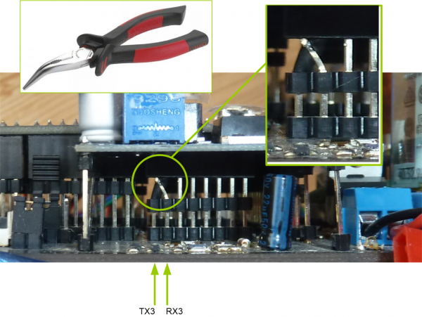
The pins TX3 and RX3 are incorrectly routed on PCB1.3 - Fix it by swapping the TX3 and RX3 pin headers as shown below.
You can see the fixing process in this video: https://youtu.be/T-EqU5azCAU?t=140
PCB1.3 odometry divider
The PCB1.3 odometry divider should be configured as follows:
RTK base
WARNING: Handle your GPS modules with care, it is an expensive piece of hardware. If you have any doubt, or if you are unsure, please ask in the Ardumower forum for help.
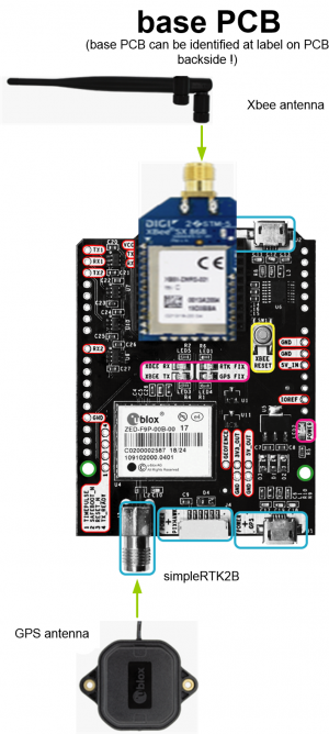
1. Make sure you have the simpleRTK2B module marked as 'BASE' in your hands (look at simpleRTK2B PCB label at backside!)
2. Connect Xbee LongRange dipole antenna
3. Connect GPS multifrequency patch antenna. NOTE: antenna cable is very sensitive, never bend the antenna cable!
4. Connect a USB 5v power supply to the USB port marked as 'POWER+GPS'
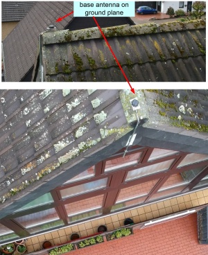
5. Install the GPS base antenna - it should have clear view to the sky in all directions without any obstacles. For best results install GPS antenna on the roof. Alternatively, if you have an open area (without trees and other obstacles), you can install the base antenna on a tripod.
NOTE: The robot mower will get and save all position coordinates relative to the base antenna (East, North) - do not move the base antenna after recording the virtual perimeter with the phone app.
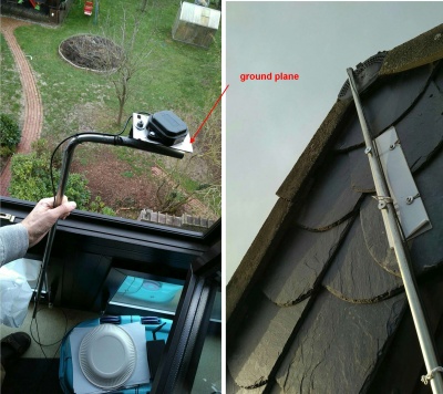
6. Improving position solution robustness: for robust position solutions (FIX), you will need to install a (conductive) ground plane (10x10cm, make it round if possible) for the patch antenna. Install the patch antenna on top of it like shown below. This will get you most robust position results.
RTK rover
WARNING: Handle your GPS modules with care, it is an expensive piece of hardware. If you have any doubt, or if you are unsure, please ask in the Ardumower forum for help.
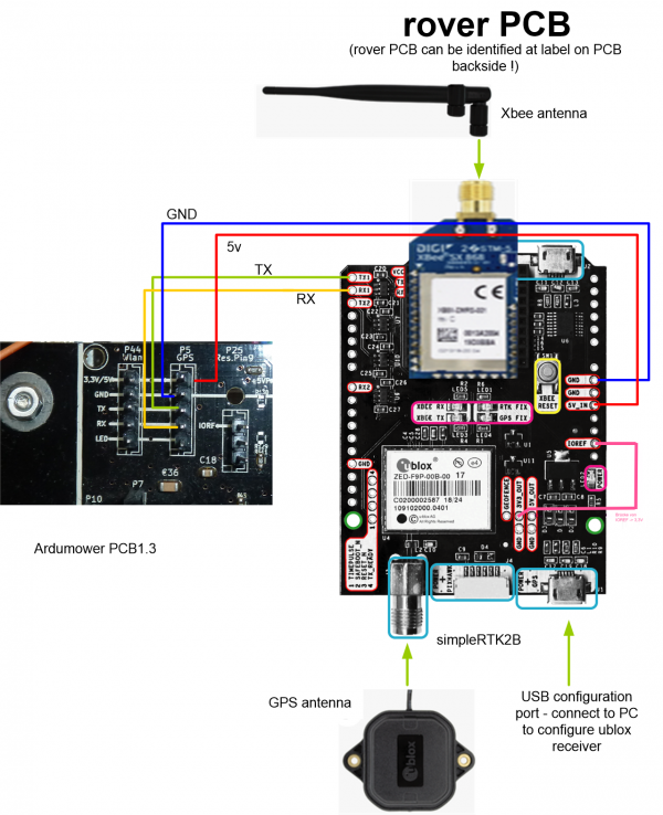
1. Make sure you have the simpleRTK2B module marked as 'ROVER' in your hands (look at simpleRTK2B PCB label at backside!)
2. Connect XBee LongRange dipole antenna
3. Connect GPS multifrequency patch antenna
4. Connect PCB1.3_GPS_GND to simpleRTK2B GND
5. Connect PCB1.3_GPS_5V to simpleRTK2B 5V_IN
6. Connect PCB1.3_GPS_TX to simpleRTK2B TX1
7. Connect PCB1.3_GPS_RX to simpleRTK2B RX1
8. Connect simpleRTK2B IOREF to simpleRTK2B 5V_OUT (to choose signal voltage level 5v)
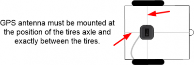
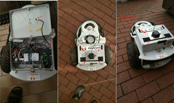
9. Install XBee antenna and GPS antenna on the Ardumower. The GPS antenna must be mounted at the position of the tire axle and between both tires (also known as 'control point' - see below):
10. Improving position solution robustness: for robust position solutions (FIX), you will need to install a (conductive) ground plane (10x10cm, make it round if possible) for the patch antenna. Place the patch antenna on top of it like shown below. This will get you most robust position results. Note: you do not have to ground the ground plane as the contact to antenna is capacitive.
Rover configuration (messages)
![]() WARNING: Only apply the steps below for the ROVER module - not for the BASE module!!
WARNING: Only apply the steps below for the ROVER module - not for the BASE module!!![]()
NOTE: If you purchased your RTK-GPS modules at Marotronics, these modules should be pre-configured and you can skip this section.
1. IMPORTANT: Make sure the Ardumower is turned off!
2. Connect SimpleRTK ROVER module USB port marked as 'POWER+GPS' to your PC.
3. Download ublox u-Center and start it: https://www.u-blox.com/en/product/u-center
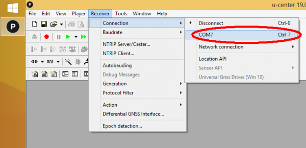
4. Choose 'Receiver->Connection' and choose your rover module COM port.
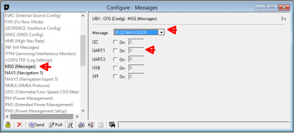
5. In this step we want to turn off all broadcast messages except one. Choose 'View->Configuration View'. Choose configuration message 'MSG (Messages)' and select one message after the other in the list (0A-37 MON-HW3, 0A-09 MON-HW, ..., etc.). For each message, make sure the selected message is turned off for UART1. Do NOT change anything for the ports UART2, USB etc. - only turn off all messages for UART1. Example for message '01-22 NAV-CLOCK' that has been deactivated for UART1:
Repeat this step for all messages in the listbox and turn off all messages for UART1.
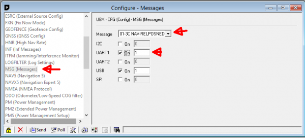
6. Finally, activate message '01-3C NAV-RELPOSNED' for UART1 (this is the only message we want to be broadcast).
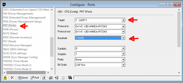
7. Choose configuration message 'PRT (Ports)', choose 'UART1', and set baudrate to 115200 for UART1:
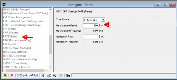
8. Choose configuration message 'RATE (Rates)' and set measurement period to 200ms (5 Hz):
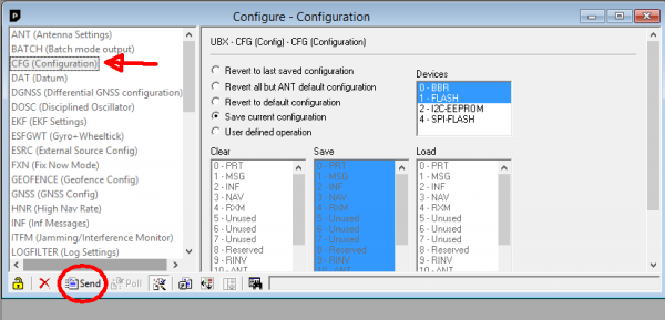
9. Choose configuration message 'CFG (Configuration)' and click on 'Send' to make the configuration in the rover persistent when the rover module is powered off.
10. Verify that the configuration is actually persistent in the rover module - disconnect the rover module and reconnect. Then go through all previous steps and verify that the configuration is still present.
11. IMPORTANT: Disconnect USB cable from rover module!
Download, Arduino Code, Firmware
In this section you will upload the Arduino code ('Sunray Firmware') to your Ardumower.
1. Download Ardumower Sunray Firmware and unzip it: https://github.com/Ardumower/Sunray/archive/master.zip
2. Open the Arduino sketch 'sunray.ino'.
3. Start Arduino IDE, and upload the sketch to your Arduino Due on the Ardumower PCB1.3.
2. After uploading, start your Ardumower - after a short while you should hear a 'beep'. Ardumower is now ready for your commands!
Phone App
In this section you will download the App to your phone (Android or iOS) which is used to configure your mower.
1. Download Viewer App:
  For Android, download Evothings Viewer: https://play.google.com/store/apps/details?id=com.evothings.evothingsviewer
  For iOS, download CGTek Viewer: https://apps.apple.com/de/app/cgtek-viewer/id1135118284
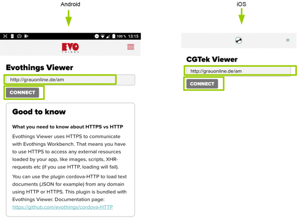
2. Start App and enter the connection URL as show below and press 'Connect':
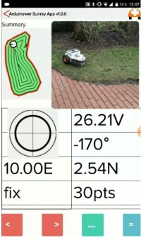
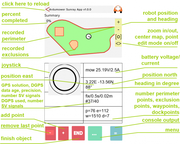
3. The App should start as shown below:
NOTE: The robot mower will get and save all position coordinates relative to the base antenna (East, North) - do not move the base antenna after recording the virtual perimeter.
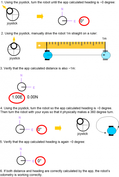
Odometry test
Both, the robot's motor odometry and GPS-RTK are used to localized the robot. Therefore, it is important to verify that the odometry is working correctly as shown below. Start the phone app and follow the steps below to verify that your mower odometry is configured correctly. For this test, make sure that your RTK is turned off (e.g. RTK base module is turned OFF)!
RTK GPS test (invalid, float, fix)
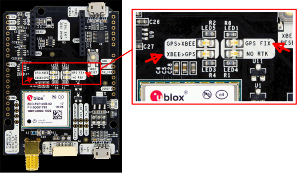
The base and rover LEDs can be used for trouble-shooting. Verify that the LEDs are acting as described below.
The base and rover LEDs should be as follows:
| GPS>XBEE | should blink - your base module is sending satellite reference data to your rover module (via the XBee module) |
| XBEE>GPS | should be OFF - your base module should not receive any XBee signal |
| GPS FIX | should be ON - your base module has found a valid GPS signal |
| NO RTK | should be ON - your base module is not performing RTK (real time kinematic) |
| GPS>XBEE | should be OFF - your rover module should not send any XBee signal |
| XBEE>GPS | should blink - your rover module is receiving satellite reference data from your base module (via the XBee module) |
| GPS FIX | should be ON - your rover module has found a valid GPS signal |
| NO RTK | should be OFF - your rover module has found a RTK FLOAT or FIX (is performing real-time kinematic) |
Depending on the robot's location (e.g. near trees), it may take some time to get a RTK FIX solution. Also, it appears this RTK FIX can get lost quickly in the first minutes (e.g. near trees). However, after several minutes running time, the RTK FIX is more robust (even near trees). So, for best position results, let the GPS 'warm-up' some minutes at a location with good sky view.
Discussion / questions / forum thread
If you have any doubt, or if you are unsure, please ask in the Ardumower forum for help:
Link to forum: https://forum.ardumower.de/threads/sunray-firmware-goes-rtk.23690/
How the waypoints are generated
This section describes how the waypoints are calculated based on the recorded perimeter polygon and the recorded exclusion polygons.
