AzuritBer Pi Firmware RFID(English): Unterschied zwischen den Versionen
(→Setting) |
(→Setting) |
||
| Zeile 88: | Zeile 88: | ||
[[Datei:Piardu rfid 50.png|400px]] | [[Datei:Piardu rfid 50.png|400px]] | ||
| − | When tag 8ECDDB95 is find AND mower Status is BACK_TO_STATION , Mower stop tracking roll -82 Degree ,stop to read perimeter signal ,run at new PWM speed of 200 for the next 10 meters , roll again -90 and run for 0.5 meters ,Start the Sender over WIFI,Check if signal is OK and start to find again perimeter wire to mow on the new area. | + | When tag 8ECDDB95 is find AND mower Status is BACK_TO_STATION , Mower stop tracking roll -82 Degree ,Stop the AREA2 or 3 Sender over WIFI , stop to read perimeter signal ,run at new PWM speed of 200 for the next 10 meters , roll again -90 and run for 0.5 meters ,Start the AREA1 Sender over WIFI, Check if signal is OK and start to find again perimeter wire to mow on the new area. |
| − | + | ||
---- | ---- | ||
Version vom 7. Dezember 2020, 14:25 Uhr
Level 3 Raspberry Pi + RFID Reader
Using Rfid reader and card locate on the perimeter wire ,mower can mow on multiple area or change direction and have different behaviour (Fast start,Fast return,escape from island,Change tracking speed etc...)
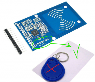
After testing many Reader only this one (PN5180) can read card at more than 10 cm and detect it after year under grass.
Hardware connecting
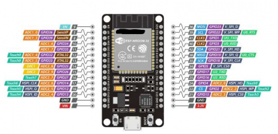
You need : PN5180 reader board , some card , ESP32 DEV KIT V1 (or later but with same pin diagram).
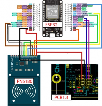
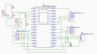
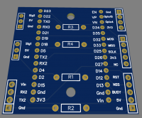
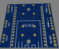
PN5180 use SPI interface to communicate with ESP32 and ESP32 DEV KIT replace the bluetooth module HC05 to communicate with PCB1.3, so you can build a small PCB to connect all wire, or order some of them from JLCPCB for example (The same board is also use to build the WIFI sender.)
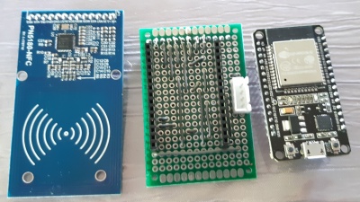
Here the first version with wrap on small PCB:
and the PCB (see easyeda and file locate on AZURITBER github) use to connect everything (Rfid reader / PCB1.3 / Wifi sender)
Put PN5180 board inside your platform as near as possible form ground (Max 10 CM) , no problem with motor or other electronic noise.
Using arduino IDE , You can download firmware inside ESP32 to have everything working : https://github.com/Boilevin/AzuritBer/tree/master/ESP32_RFID
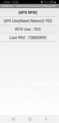
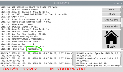
If everything is OK you can see Last Rfid tag code in console or into Arduremote each time you move a tag near the reader
Setting
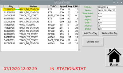
Into Piardu in menu RFID you can choose what you want the mower do:
2 Value need to match to have a mower react (TODO) : TAG Nr AND Mower STATUS
The same tag can be use to different behaviour.
According Tag Nr read and Status of mower ( "BACK_TO_STATION" or "TRACK_TO_START" or "WIRE_MOWING" )
Mower can DO : 'RTS' or 'FAST_START' or 'SPEED' or 'NEW_AREA'
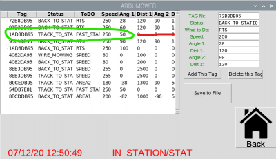
Here example of RTS it is return to station and can be use to escape from island or simply fast return to station :
When tag 1AD8DB95 is find AND mower Status is TRACK_TO_START , Mower stop tracking roll 28 Degree and run at new PWM speed of 250 to find again the wire and continue tracking.
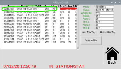
Here example of FAST_START it can be use to go very fast from one location on the wire to other one when tracking to find a new area :
When tag 72B8DB95 is find AND mower Status is BACK_TO_STATION , Mower stop tracking roll 50 Degree and run at new PWM speed of 250 to find again the wire and continue tracking.
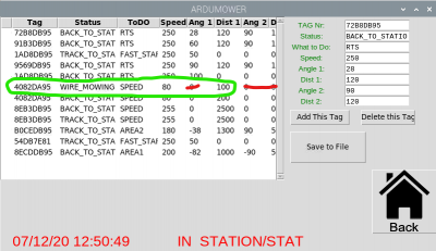
Here example of new speed it can be use to Dock at low speed or simply change tracking speed when you want :
When tag 4082DA95 is find AND mower Status is WIRE_MOWING , Mower continue tracking but run at new PWM speed of 80 for next 100 cm.
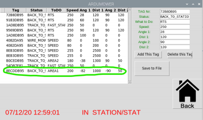
Here example of area change it can be use to Go to a new mowing area (with other sender) :
When tag 8ECDDB95 is find AND mower Status is BACK_TO_STATION , Mower stop tracking roll -82 Degree ,Stop the AREA2 or 3 Sender over WIFI , stop to read perimeter signal ,run at new PWM speed of 200 for the next 10 meters , roll again -90 and run for 0.5 meters ,Start the AREA1 Sender over WIFI, Check if signal is OK and start to find again perimeter wire to mow on the new area.
