AzuritBer RFID option (English): Unterschied zwischen den Versionen
(Die Seite wurde neu angelegt: „Test“) |
|||
| Zeile 1: | Zeile 1: | ||
| − | + | ||
| + | It's the standard PCB1.3 or 1.4 and BT module is ESP32 one , a PN5180 RFID reader is connected to the ESP32 | ||
| + | |||
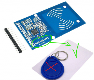
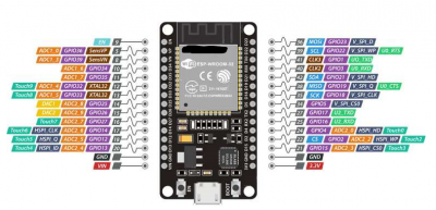
| + | You need : PN5180 reader board , some card , '''ESP32 DEV KIT V1''' (or later but with same pin diagram). | ||
| + | |||
| + | [[Datei:PN5180.png|400px]] [[Datei:esp32 layout.png|400px]] | ||
| + | ---- | ||
| + | |||
| + | |||
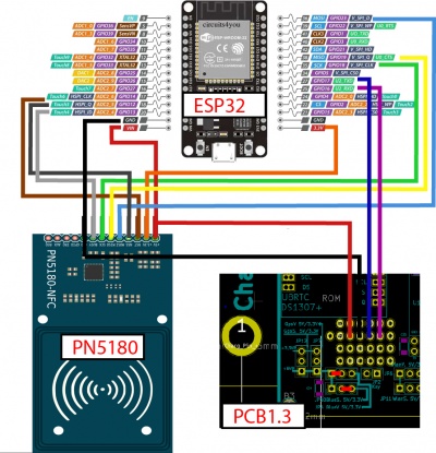
| + | PN5180 use SPI interface to communicate with ESP32 and ESP32 DEV KIT replace the bluetooth module HC05 to communicate with PCB1.3, so you can build a small PCB to connect all wire, or order some of them from JLCPCB for example (The same board is also use to build the WIFI sender.) | ||
| + | |||
| + | |||
| + | [[Datei:rfid wiring.jpg|400px]] | ||
| + | |||
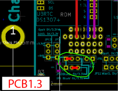
| + | Do not forget the jumper JP4 and JP10 | ||
| + | |||
| + | [[Datei:Rfid wiring jumper.png|400px]] | ||
| + | |||
| + | ---- | ||
| + | |||
| + | |||
| + | Here the first version with wrap on small PCB: | ||
| + | |||
| + | [[Datei:rfid esp32.jpg|400px]] | ||
| + | ---- | ||
| + | |||
| + | and the PCB (see easyeda and file locate on AZURITBER github) use to connect everything (Rfid reader / PCB1.3 / Wifi sender) | ||
| + | |||
| + | [[Datei:Rfid wiring 10 .png|200px]] [[Datei:Rfid wiring 20 .png|200px]] [[Datei:Rfid wiring 30 .png|200px]] | ||
| + | ---- | ||
| + | |||
| + | Put PN5180 board inside your platform as near as possible form ground (Max 10 CM) , no problem with motor or other electronic noise. | ||
| + | |||
| + | Using arduino IDE , You can download firmware inside ESP32 to have everything working : | ||
| + | https://github.com/Boilevin/AzuritBer/tree/master/ESP32_RFID | ||
| + | |||
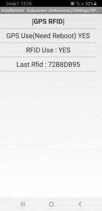
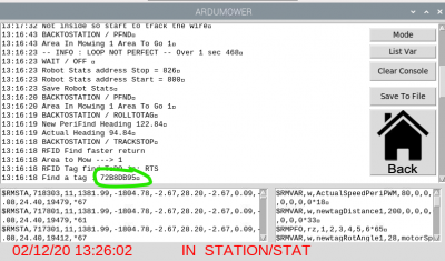
| + | If everything is OK you can see '''Last Rfid''' tag code in console or into Arduremote each time you move a tag near the reader | ||
| + | |||
| + | [[Datei:ArduRemote Setting gps rfid.jpg|200px]] [[Datei:Piardu console 3.png|400px]] | ||
Version vom 5. Februar 2022, 10:59 Uhr
It's the standard PCB1.3 or 1.4 and BT module is ESP32 one , a PN5180 RFID reader is connected to the ESP32
You need : PN5180 reader board , some card , ESP32 DEV KIT V1 (or later but with same pin diagram).
PN5180 use SPI interface to communicate with ESP32 and ESP32 DEV KIT replace the bluetooth module HC05 to communicate with PCB1.3, so you can build a small PCB to connect all wire, or order some of them from JLCPCB for example (The same board is also use to build the WIFI sender.)
Do not forget the jumper JP4 and JP10
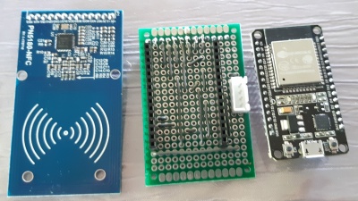
Here the first version with wrap on small PCB:
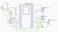
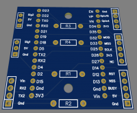
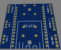
and the PCB (see easyeda and file locate on AZURITBER github) use to connect everything (Rfid reader / PCB1.3 / Wifi sender)
Put PN5180 board inside your platform as near as possible form ground (Max 10 CM) , no problem with motor or other electronic noise.
Using arduino IDE , You can download firmware inside ESP32 to have everything working : https://github.com/Boilevin/AzuritBer/tree/master/ESP32_RFID
If everything is OK you can see Last Rfid tag code in console or into Arduremote each time you move a tag near the reader
