Bluetooth und App: Unterschied zwischen den Versionen
(→Bluetooth Module) |
(→Die Schritte im Einzelnen) |
||
| (21 dazwischenliegende Versionen von 3 Benutzern werden nicht angezeigt) | |||
| Zeile 1: | Zeile 1: | ||
=Zusammenfassung= | =Zusammenfassung= | ||
| + | |||
| + | [[File: Pfodapp_menu.png | 600px]] | ||
| + | |||
Der Ardumower kann drahtlos überwacht und gesteuert werden: | Der Ardumower kann drahtlos überwacht und gesteuert werden: | ||
* über Handy/Tablet (Android App) | * über Handy/Tablet (Android App) | ||
* über USB Bluetooth Dongle (PC serial console) | * über USB Bluetooth Dongle (PC serial console) | ||
| − | Auf den Handy/Tablet benötigst du folgende App [https://play.google.com/store/apps/details?id= | + | Auf den Handy/Tablet benötigst du folgende App [https://play.google.com/store/apps/details?id=de.grauonline.arduremote 'ArduRemote']. alternativ kannst du diese App benutzen [https://play.google.com/store/apps/details?id=au.com.forward.pfodApp 'pfodApp']. |
Das Handy-Menü enthält: | Das Handy-Menü enthält: | ||
| Zeile 21: | Zeile 24: | ||
=Bluetooth Module= | =Bluetooth Module= | ||
| − | + | Am Roboter wird das Bluetooth-Modul HC-05 verwendet, welches das das Serial Port Profil (SPP) unterstützt. SPP verwendet das Bluetooth Service Discovery Protocol (SDP) und das RFCOMM protocol. | |
| − | + | ||
| − | + | ||
| − | + | ||
=Bluetooth HC-05= | =Bluetooth HC-05= | ||
<gallery> | <gallery> | ||
| − | File: | + | File: Pcb_bluetooth.jpg | PCB and HC-05 module |
| − | File: HC-05 schematics.jpg | HC-05 | + | File: Bluetooth_module.jpg | HC-05 Modul |
| + | File: HC-05 schematics.jpg | HC-05 Schaltung | ||
| + | File: HC-05.gif | HC-05 mit Taster | ||
</gallery> | </gallery> | ||
| − | + | Zur Programmierung wird der Key-Pin des BT-Modules mit 3,3V vom Arduino verbunden und danach die Verbindung wieder getrennt. | |
| − | + | Wiring: | |
| − | =Schritte= | + | Bluetooth HC05 VCC --- PCB VCC |
| − | # | + | Bluetooth HC05 GND --- PCB GND |
| − | ## | + | Bluetooth HC05 TX --- PCB RX |
| − | ## | + | Bluetooth HC05 RX --- PCB TX |
| − | ## | + | |
| − | # | + | Besonderheiten: Je nach Lieferant wird das HC-05 Modul mit 5 Volt VCC betrieben; Aufschrift "Power 3.6-6V"(JP 8 anstelle von JP 9 setzen). Sofern sich am Pin "EN" ein Microtaster befindet (siehe Foto), so muss dieser während der Konfiguration gedrückt sein, da ansonsten das Modul nicht erkannt wird. Key-Pin muss wie beschrieben auf +3,3 Volt gesetzt sein (JP 2). Rx/Tx laufen auch hier mit 3,3 Volt. |
| − | # | + | |
| − | # Pairing: | + | =Die Schritte im Einzelnen= |
| − | # pfodApp: | + | # Konfigurationsmodus: Das Bluetooth-Modul muss für die nächsten Schritte im Konfigurationsmodus sein: |
| + | ## für HC05: Nachdem das Modul an die Betriebsspannung angeschlossen wurde, verbinde den KEY-Pin mit 3,3V | ||
| + | ## für HC06/linvor: nicht paaren/verbinden (LED muss blinken) | ||
| + | ## für FBT06/MBTV4: Zuerst muss ein dünner Draht von Pin PIO11 nach VCC (PIN 12)das sind 3.3 Volt gelötet werden. | ||
| + | # Baudrate: Das Bluetooth-Modul und der Arduino Mega müssen die gleiche Baudrate (19200) verwenden - Die Baudrate des Bluetooth-Modules kann über die serielle Konsole des Ardumowers geändert werden. Verbinde das Ardumower Mega Board mit deinem PC (USB), gehe in die serielle Konsole in der Arduino IDE (Strg+M), und wähle dort Baudrate 19200, dann drücke Taste 'd' um ins Ardumower-Menü zu gelangen, dann Taste '3' for Kommunikationsmenü, dann Taste '3' um die richtige Baudrate für das BT-Modul einzustellen. | ||
| + | # Neustart: Nachdem das BT-Modul erfolgreich konfiguriert wurde, muss die Verbindung des KEY-Pins zu 3,3V wieder getrennt werden (HC05). Danach startet man das Modul neu. | ||
| + | # Pairing: Das BT-Modul muss dem Handy oder Tablet (über Android/Einstellungen) bekanntgemacht werden. Diesen Vorgang nennt man Pairing. Wähle auf dem Android-Gerät das Symbol "Einstellungen" (über Android Menü). Nun wähle "Drahtlos und Netzwerke/Bluetooth->Bluetooth Einstellungen" und "Finde Gerät(Scannen)". Wurde der Ardumower in der Liste der gefundenen Geräte angezeigt, wählt man ihn aus und sagt dann -verbinden-. Nach der Eingabe der Sicherheits-PIN (als Vorgabe "1234"), sollte das Bluetooth-Modul des Arduino mit dem Handy gepaart sein (paired). | ||
| + | # pfodApp: Jetzt kann die APP pfodApp/ArduRemote gestartet werden und sich mit dem Ardumower verbinden. | ||
| + | # Nach erfolgreichem Verbinden leuchtet die Diode D8. | ||
=Kommunikation-Protokoll= | =Kommunikation-Protokoll= | ||
| − | + | Das Kommunikation-Protokoll für die Verbindung zwischen Roboter und Androis-App (die 'pfodSpecification') ist hier definiert: http://www.forward.com.au/pfod/. | |
| − | + | Alle Menüs (Menüpunkte, Schieberegler, Taster) werden innerhalb der Robotersoftware definiert. Die App stellt die kreierten Menüs nur dar und sendet einen Befehl zurück, wenn ein Menüpunkt durch den Benutzer angeklickt wurde. | |
| − | + | Beispiel Kommunikation: | |
| − | 1. App | + | 1. App verlangt das Hauptmenü: {.} |
| − | 2. | + | 2. Roboter sendet Hauptmenü zur App: {.title`1000|key1~text1|key2~text2|key3~text3} |
| − | + | Die App stellt das Hauptmenü wie folgt dar: | |
title | title | ||
| Zeile 63: | Zeile 73: | ||
[text3] | [text3] | ||
| − | 3. | + | 3. Der Benutzer klickt den Menüpunkt 'text1' an, die App sendetden entsprechenden Befehl {key1} zurück |
| − | + | Man kann die Kommunikation protokollieren und in einer Datei auf dem Handy/Tablet speichern (Ordner 'pfodAppRawData' or 'ArduRemote'). In ArduRemote, muss man noch die 'Android Menütaste' drücken und 'Enable logging' wählen. | |
<gallery> | <gallery> | ||
| − | File: Android_menu_button.png | Android | + | File: Android_menu_button.png | Android Menütaste |
</gallery> | </gallery> | ||
=Sensor-Protokollierung= | =Sensor-Protokollierung= | ||
| − | + | For PC data analysis, algorithm modelling and optimization, you can collect robot sensor data using pfodApp like this: | |
| + | |||
| + | # Using your Android pfodApp, connect to your robot and choose 'Log sensors'. The logged sensor data will be displayed. Click 'Back' to stop logging (NOTE: for ArduRemote, press Android menu button before and choose 'Enable logging' to enable file logging). | ||
| + | # Connect your Android phone to the PC, if being asked on the phone choose 'Enable as USB device', so you phone shows as a new Windows drive on your PC. | ||
| + | # On your PC, launch Windows Explorer and choose the new Android drive, browse to the 'pfodAppRawData' folder (for ArduRemote: 'ArduRemote' folder), and copy the data file to your PC (you can identify files by their Bluetooth name and date). | ||
| + | |||
| + | <gallery> | ||
| + | File: Pfodapp_start.png | 1. Start pfodApp | ||
| + | File: Pfodapp_log_sensors.png | 2. Choose 'Log sensors' | ||
| + | File: Pfodapp_log_sensors_exit.png | 3. Choose phone back button or 'Exit' | ||
| + | File: Android_enable_usb device.png | 4. Connect to your PC via USB, choose 'Enable as USB device' | ||
| + | File: log_sensor.png | 5. Using Windows explorer, browse to folder 'pfodAppRawData' on external Android drive to access sensor log file | ||
| + | </gallery> | ||
=Videos= | =Videos= | ||
Aktuelle Version vom 6. April 2017, 09:51 Uhr
Inhaltsverzeichnis
Zusammenfassung

Der Ardumower kann drahtlos überwacht und gesteuert werden:
- über Handy/Tablet (Android App)
- über USB Bluetooth Dongle (PC serial console)
Auf den Handy/Tablet benötigst du folgende App 'ArduRemote'. alternativ kannst du diese App benutzen 'pfodApp'.
Das Handy-Menü enthält:
- Statusinformationen (Akku-Spannungg, Ladestrom usw.)
- Einstellungen (Timer usw.)
- Abgleich (Motor, IMU etc.)
- Fernsteuerung (Start/Stop, Ein/Aus Mähmotor, Messermodulation usw.)
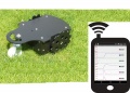
Live-Konfiguration, Überwachung und Fehlersuche
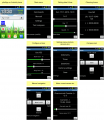
Android App Menü

Android App (pfodApp)

Android App (ArduRemote)
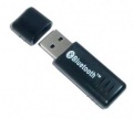
PC-Kommunikation über Bluetooth USB Dongle


Bluetooth Module
Am Roboter wird das Bluetooth-Modul HC-05 verwendet, welches das das Serial Port Profil (SPP) unterstützt. SPP verwendet das Bluetooth Service Discovery Protocol (SDP) und das RFCOMM protocol.
Bluetooth HC-05
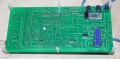
PCB and HC-05 module
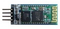
HC-05 Modul
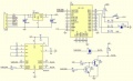
HC-05 Schaltung
HC-05 mit Taster


Zur Programmierung wird der Key-Pin des BT-Modules mit 3,3V vom Arduino verbunden und danach die Verbindung wieder getrennt.
Wiring:
Bluetooth HC05 VCC --- PCB VCC
Bluetooth HC05 GND --- PCB GND
Bluetooth HC05 TX  --- PCB RX
Bluetooth HC05 RX  --- PCB TX
Besonderheiten: Je nach Lieferant wird das HC-05 Modul mit 5 Volt VCC betrieben; Aufschrift "Power 3.6-6V"(JP 8 anstelle von JP 9 setzen). Sofern sich am Pin "EN" ein Microtaster befindet (siehe Foto), so muss dieser während der Konfiguration gedrückt sein, da ansonsten das Modul nicht erkannt wird. Key-Pin muss wie beschrieben auf +3,3 Volt gesetzt sein (JP 2). Rx/Tx laufen auch hier mit 3,3 Volt.
Die Schritte im Einzelnen
- Konfigurationsmodus: Das Bluetooth-Modul muss für die nächsten Schritte im Konfigurationsmodus sein:
- für HC05: Nachdem das Modul an die Betriebsspannung angeschlossen wurde, verbinde den KEY-Pin mit 3,3V
- für HC06/linvor: nicht paaren/verbinden (LED muss blinken)
- für FBT06/MBTV4: Zuerst muss ein dünner Draht von Pin PIO11 nach VCC (PIN 12)das sind 3.3 Volt gelötet werden.
- Baudrate: Das Bluetooth-Modul und der Arduino Mega müssen die gleiche Baudrate (19200) verwenden - Die Baudrate des Bluetooth-Modules kann über die serielle Konsole des Ardumowers geändert werden. Verbinde das Ardumower Mega Board mit deinem PC (USB), gehe in die serielle Konsole in der Arduino IDE (Strg+M), und wähle dort Baudrate 19200, dann drücke Taste 'd' um ins Ardumower-Menü zu gelangen, dann Taste '3' for Kommunikationsmenü, dann Taste '3' um die richtige Baudrate für das BT-Modul einzustellen.
- Neustart: Nachdem das BT-Modul erfolgreich konfiguriert wurde, muss die Verbindung des KEY-Pins zu 3,3V wieder getrennt werden (HC05). Danach startet man das Modul neu.
- Pairing: Das BT-Modul muss dem Handy oder Tablet (über Android/Einstellungen) bekanntgemacht werden. Diesen Vorgang nennt man Pairing. Wähle auf dem Android-Gerät das Symbol "Einstellungen" (über Android Menü). Nun wähle "Drahtlos und Netzwerke/Bluetooth->Bluetooth Einstellungen" und "Finde Gerät(Scannen)". Wurde der Ardumower in der Liste der gefundenen Geräte angezeigt, wählt man ihn aus und sagt dann -verbinden-. Nach der Eingabe der Sicherheits-PIN (als Vorgabe "1234"), sollte das Bluetooth-Modul des Arduino mit dem Handy gepaart sein (paired).
- pfodApp: Jetzt kann die APP pfodApp/ArduRemote gestartet werden und sich mit dem Ardumower verbinden.
- Nach erfolgreichem Verbinden leuchtet die Diode D8.
Kommunikation-Protokoll
Das Kommunikation-Protokoll für die Verbindung zwischen Roboter und Androis-App (die 'pfodSpecification') ist hier definiert: http://www.forward.com.au/pfod/.
Alle Menüs (Menüpunkte, Schieberegler, Taster) werden innerhalb der Robotersoftware definiert. Die App stellt die kreierten Menüs nur dar und sendet einen Befehl zurück, wenn ein Menüpunkt durch den Benutzer angeklickt wurde.
Beispiel Kommunikation:
1. App verlangt das Hauptmenü: {.}
2. Roboter sendet Hauptmenü zur App: {.title`1000|key1~text1|key2~text2|key3~text3}
   Die App stellt das Hauptmenü wie folgt dar:
   title
   [text1]
   [text2]
   [text3]
3. Der Benutzer klickt den Menüpunkt 'text1' an, die App sendetden entsprechenden Befehl {key1} zurück
Man kann die Kommunikation protokollieren und in einer Datei auf dem Handy/Tablet speichern (Ordner 'pfodAppRawData' or 'ArduRemote'). In ArduRemote, muss man noch die 'Android Menütaste' drücken und 'Enable logging' wählen.
Android Menütaste

Sensor-Protokollierung
For PC data analysis, algorithm modelling and optimization, you can collect robot sensor data using pfodApp like this:
- Using your Android pfodApp, connect to your robot and choose 'Log sensors'. The logged sensor data will be displayed. Click 'Back' to stop logging (NOTE: for ArduRemote, press Android menu button before and choose 'Enable logging' to enable file logging).
- Connect your Android phone to the PC, if being asked on the phone choose 'Enable as USB device', so you phone shows as a new Windows drive on your PC.
- On your PC, launch Windows Explorer and choose the new Android drive, browse to the 'pfodAppRawData' folder (for ArduRemote: 'ArduRemote' folder), and copy the data file to your PC (you can identify files by their Bluetooth name and date).
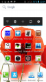
1. Start pfodApp
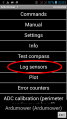
2. Choose 'Log sensors'
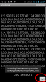
3. Choose phone back button or 'Exit'
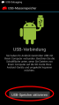
4. Connect to your PC via USB, choose 'Enable as USB device'
5. Using Windows explorer, browse to folder 'pfodAppRawData' on external Android drive to access sensor log file


