Charging: Unterschied zwischen den Versionen
(→Battery) |
(→Undervoltage protection) |
||
| Zeile 30: | Zeile 30: | ||
Idea: | Idea: | ||
| − | Emergency push button: can power-off the robot immediately | + | *Emergency push button: can power-off the robot immediately |
| − | POWER/START button: switches on operation voltage | + | *POWER/START button: switches on operation voltage |
| − | Arduino power signal pin (OUT): set to HIGH at bootup - set to LOW if undervoltage detected | + | *Arduino power signal pin (OUT): set to HIGH at bootup - set to LOW if undervoltage detected |
Version vom 7. April 2015, 16:11 Uhr
Inhaltsverzeichnis
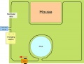
Basic principle
By the help of the perimeter wire loop, the robot finds its charging station where it can be charged again. So, it drives along the perimeter wire (in clock-wise direction) until it detects a charging voltage at its charging pins. There the robot stops and recharges its battery.
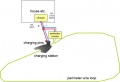
Perimeter wire below charging station
Charging station components
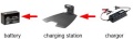
Charging station
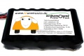
Sony Konion 7S2P battery pack (29.4V, 4500 mAh)


Charger
For the charger, we are using a Lithium Ion e-bike charger (29.4V, 1.5A current limitting) that can be purchased via the shop ![]() . The charger is placed in a protected area (house etc.) and connected to the robot charging station. The charger should accomplish the following things (in this case Lithium-Ion, lead battery is similar, but less critical):
. The charger is placed in a protected area (house etc.) and connected to the robot charging station. The charger should accomplish the following things (in this case Lithium-Ion, lead battery is similar, but less critical):
- Charge battery pack via the charging pins of the robot
- Maximum cutoff voltage / charge voltage compliance (charging voltage limit)
- Maximum charging current compliance (charging current limit)
If you are using an existing charger, these things are implemented with high probability already in it.
Battery
For the battery, we are using a 'Sony Konion 7S2P' Lithium Ion battery pack (Sony Konion US18650V3 2250 mAh cells, Li-Mn), 29.4V, 4500 mAh, 500 recharge cycles, 126 x 36 x 65 mm (LBH).
Using this battery with the Ardumower motors, the mowing time is about one hour.
Undervoltage protection
The robot should be able to switch off the battery itself (undervoltage protection).
Idea:
- Emergency push button: can power-off the robot immediately
- POWER/START button: switches on operation voltage
- Arduino power signal pin (OUT): set to HIGH at bootup - set to LOW if undervoltage detected
battery (+) ---- emergency push button (emergency OFF) ----- relay switch ------ operation voltage (+)
                                                                  |
                                                                  |
                                                               control
POWER/START button -----diode-------------------------------------|
                                                                  |
Arduino power signal pin (OUT) -----diode-------------------------|

battery (-)
Robot
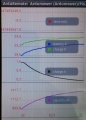
In the robot itself, the battery voltage is monitored (see diagram below). So it can be determined when the robot must go to the charging station. The robot and the voltage and the current during charging is controlled. So it can be determined whether the robot has reached the charger and when the battery is fully charged again. Ideally, the charging station also powers the loop transmitter:
charging station circuit:
 Power supply => Charger 24V (+)----- Charging station charger pin(+)
                 GND         (-)----- Charging station charger pin(-)
                 Charger 24V (+)----- DC-DC converter 5V  => Perimeter sender Arduino Nano
                 Charger 24V (+)----- DC-DC converter 12V => Perimeter sender MC motor driver
robot charging circuit:
 Charging station (+)---+------+-- relais ---- current sensor ----- battery (+)
                               |
                               ---- voltage sensing
 Charging station (-)-- +------------------------------------------ battery (-)
Charge monitoring/Battery settings
Via pfodApp (Android) you can monitor the charging process.
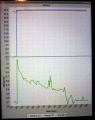
Charging plot
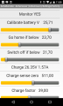
Battery settings
Battery fully charged


Charging station ideas


Videos