Chassis 2021: Unterschied zwischen den Versionen
BenPan (Diskussion | Beiträge) K |
|||
| (42 dazwischenliegende Versionen von 2 Benutzern werden nicht angezeigt) | |||
| Zeile 1: | Zeile 1: | ||
| − | <p style="color: red">This page is under construction.</p> | + | <!-- <p style="color: red">This page is under construction.</p> --> |
This page describes the assembly of the Ardumower chassis that you can purchase via the [https://www.marotronics.de/Ardumower-Rasenroboter-Set-Model-2021-auch-mit-GPS-RTK-Option shop] [[File: shopping.png|link=https://www.marotronics.de/index.php?k=32]]. | This page describes the assembly of the Ardumower chassis that you can purchase via the [https://www.marotronics.de/Ardumower-Rasenroboter-Set-Model-2021-auch-mit-GPS-RTK-Option shop] [[File: shopping.png|link=https://www.marotronics.de/index.php?k=32]]. | ||
| + | |||
| + | Related pages: | ||
| + | * [[PCB 1.3 (English)|How to solder the PCB]] | ||
| + | * [[Ardumower Sunray|All about Ardumower Sunray (GPS RTK-Version)]] | ||
| + | * [[Maintenance_Repair_Tips | Maintenance & Repair Tips]] | ||
[[File: Ardumower chassis2021 weiß.jpg | 500px]] | [[File: Ardumower chassis2021 weiß.jpg | 500px]] | ||
| Zeile 10: | Zeile 15: | ||
| − | =Ardumower Chassis 2021 specifications= | + | <!-- =Ardumower Chassis 2021 specifications= --> |
| Zeile 18: | Zeile 23: | ||
#[https://www.youtube.com/watch?v=s_W-PYmOGCo Ardumower Tutorials Chassis 2021 Teil 3 Montage] | #[https://www.youtube.com/watch?v=s_W-PYmOGCo Ardumower Tutorials Chassis 2021 Teil 3 Montage] | ||
| − | = | + | =Tools= |
| − | + | ||
* Screw driver | * Screw driver | ||
* Different Imbus screw driver | * Different Imbus screw driver | ||
* Different Torx screw driver | * Different Torx screw driver | ||
* Knife | * Knife | ||
| − | |||
| − | |||
* Round and flat file | * Round and flat file | ||
| − | * | + | * sand paper or sand sponge |
* Drill machine with drill set (3,4,6,8,10 mm drills) | * Drill machine with drill set (3,4,6,8,10 mm drills) | ||
| − | == | + | =Whats inside the Box?= |
| − | + | ||
| − | + | ||
| − | + | ||
| − | + | ||
| − | + | <gallery> | |
| + | File: Chassis2021InsideBox1.png | Plates etc. | ||
| + | File: Chassis2021InsideBox2.png | Electronics, Screws | ||
| + | </gallery> | ||
| + | =Preparation of Plate-Materials= | ||
| − | + | <gallery> | |
| + | File: Chassis2021Prepare1.png | parts with sharp burrs | ||
| + | File: Chassis2021Prepare2.png | parts without sharp burrs | ||
| + | File: Chassis2021Prepare3.png | glue the doubled Motor-mounting-plates | ||
| + | </gallery> | ||
| + | ==Front-Plate== | ||
| − | + | Mount the three Sonar-Sensors with hot-glue (carefully). | |
| + | [[File:Chassis2021Prepare4.png | 500px]] | ||
| − | = | + | ==Mow-Plate== |
| + | Inserting the threaded sleeves for the mower blades. | ||
| − | + | <gallery> | |
| + | File: Chassis2021MowPlate1.png | 1 | ||
| + | File: Chassis2021MowPlate2.png | 2 | ||
| + | File: Chassis2021MowPlate3.png | 3 | ||
| + | </gallery> | ||
| + | =Wiring= | ||
| + | |||
| + | There are two options to wire the emergency switch. Option 2 is the recommended version. If you realize version 1, don´t forget an external accessible power-Switch (close to "connector") . | ||
| + | |||
| + | [[File:Chassis2021EmergencyStop.png | 500px]] | ||
| + | |||
| + | =Case assembly= | ||
| − | + | <gallery> | |
| + | File: Chassis2021Assembly1.png | Arrange parts and drill two holes for bumper cabling (see right hand finger for one of the marks) | ||
| + | File: Chassis2021Assembly2.png | Mount profiles to baseplate and gear-motors to side walls (with especially marked screws "Motor") | ||
| + | File: Chassis2021Assembly3.png | Mount profile for mowing motor | ||
| + | File: Chassis2021Assembly4.png | Install sealing ring | ||
| + | File: Chassis2021Assembly5.png | install mowing motor | ||
| + | File: Chassis2021Assembly6.png | mount sidewalls | ||
| + | File: Chassis2021Assembly7.png | prepare backside | ||
| + | File: Chassis2021Assembly8.png | install backside | ||
| + | File: Chassis2021Assembly9.png | prepare bumper | ||
| + | File: Chassis2021Assembly10.png | start with screws -> washers -> plastic spacer sleeves | ||
| + | File: Chassis2021Assembly11.png | add bumper -> washers -> nuts | ||
| + | File: Chassis2021Assembly12.png | finished bumper | ||
| + | File: Chassis2021Assembly13.png | install mowing plate | ||
| + | File: Chassis2021Assembly14.png | install frontplate | ||
| + | File: Chassis2021Assembly15.png | finished case | ||
| + | File: Chassis2021Assembly16.png | install electronics | ||
| + | File: Chassis2021Assembly17.png | final frontplate | ||
| + | File: Chassis2021Assembly18.png | final backplate | ||
| + | File: Chassis2021Assembly19.png | final top view | ||
| + | </gallery> | ||
=Further links= | =Further links= | ||
[https://forum.ardumower.de/threads/aufbau-anleitung-für-das-neue-dibond-chassis-mit-bumper.24067/ instructions on ardumower forum] | [https://forum.ardumower.de/threads/aufbau-anleitung-für-das-neue-dibond-chassis-mit-bumper.24067/ instructions on ardumower forum] | ||
Aktuelle Version vom 6. September 2021, 21:04 Uhr
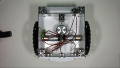
This page describes the assembly of the Ardumower chassis that you can purchase via the shop ![]() .
.
Related pages:

Please start watching the detailed instruction videos on Youtube (see section "Videos"). This page is based on the content of the videos.
Inhaltsverzeichnis
Videos
- Ardumower Tutorials Chassis 2021 Teil 1 WasGehoertDazu
- Ardumower Tutorials Chassis 2021 Teil 2 Vorbereitung
- Ardumower Tutorials Chassis 2021 Teil 3 Montage
Tools
- Screw driver
- Different Imbus screw driver
- Different Torx screw driver
- Knife
- Round and flat file
- sand paper or sand sponge
- Drill machine with drill set (3,4,6,8,10 mm drills)
Whats inside the Box?
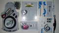
Plates etc.
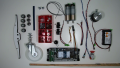
Electronics, Screws


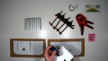
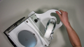
Preparation of Plate-Materials
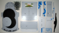
parts with sharp burrs
parts without sharp burrs
glue the doubled Motor-mounting-plates


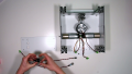
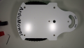
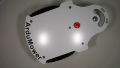
Front-Plate
Mount the three Sonar-Sensors with hot-glue (carefully).

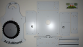
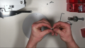
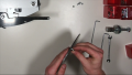
Mow-Plate
Inserting the threaded sleeves for the mower blades.
1
2
3


Wiring
There are two options to wire the emergency switch. Option 2 is the recommended version. If you realize version 1, don´t forget an external accessible power-Switch (close to "connector") .

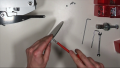
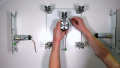
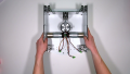
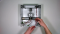
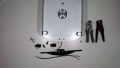
Case assembly
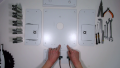
Arrange parts and drill two holes for bumper cabling (see right hand finger for one of the marks)
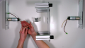
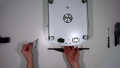
Mount profiles to baseplate and gear-motors to side walls (with especially marked screws "Motor")
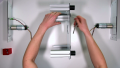
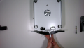
Mount profile for mowing motor
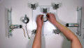
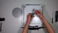
Install sealing ring
install mowing motor
mount sidewalls
prepare backside
install backside
prepare bumper
start with screws -> washers -> plastic spacer sleeves
add bumper -> washers -> nuts

finished bumper
install mowing plate
install frontplate
finished case
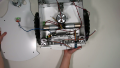
install electronics
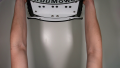
final frontplate
final backplate
final top view


