Free wheel sensor: Unterschied zwischen den Versionen
(→Download) |
(→Download) |
||
| (17 dazwischenliegende Versionen desselben Benutzers werden nicht angezeigt) | |||
| Zeile 1: | Zeile 1: | ||
=Idea= | =Idea= | ||
| − | Add a rotation sensor to the free wheel to detect motion over ground of the mower and thereby detecting obstacles. | + | Add a rotation sensor to the free wheel to detect 'motion/no motion over ground' of the mower and thereby detecting obstacles. The sensor simulates a bumper (if no motion detected it triggers like a bumper). |
| + | |||
| + | The sensor is based on a compass module (which internally measures magnetic field changes via hall sensors) and rotating magnets. | ||
[[File:Ardumower_free_wheel_parts4.jpg|300px]] | [[File:Ardumower_free_wheel_parts4.jpg|300px]] | ||
| Zeile 18: | Zeile 20: | ||
=Required components= | =Required components= | ||
| − | * Arduino Nano (placed into printed 3D part) and powered (VIN pin) via Ardumower PCB 9V output pin | + | * [https://www.marotronics.de/Nano-V30-ATmega328P-AU-MCU-Arduino-kompatibel-USB-CH340G Arduino Nano (placed into printed 3D part) and powered (VIN pin) via Ardumower PCB 9V output pin] |
| − | * HMC5883 compass sensor (placed into printed 3D part) | + | * [https://www.marotronics.de/GY-87-10DOF-MPU6050-BMP180-HMC5883L-Sensor-Arduino-Raspberry-Pi HMC5883 compass sensor (placed into printed 3D part)] |
| − | * 4 ball magnets | + | * 4 ball magnets (10mm diameter) |
* printed 3D parts | * printed 3D parts | ||
=Download= | =Download= | ||
| − | Note: the sensor simulates an Ardumower bumper (and will be connected to the PCB bumper pin): when no motion is detected, a bumper press is simulated. | + | Note: the sensor simulates an Ardumower bumper (and will be connected to the PCB bumper pin): when no motion is detected, a bumper press is simulated. Ardumower only evaluates the bumper when in driving state. |
| + | |||
| + | * [https://github.com/Ardumower/ardumower/tree/master/code/freewheel Arduino Code] | ||
| + | * [https://drive.google.com/open?id=1qjGodS3wNexXOilQUquC8CJStBHAUR9U parts for 3D printing] | ||
| − | + | =Wiring= | |
| + | Arduino Nano Vin -- Ardumower PCB 9V out | ||
| + | Arduino Nano GND -- Ardumower PCB P11 GND | ||
| + | Arduino Nano D8 -- Ardumower PCB P11 bumper sensor input (left/right) | ||
| + | Arduino Nano 5v out -- HMC5883 VCC | ||
| + | Arduino Nano GND -- HMC5883 GND | ||
| + | Arduino Nano A4 -- HMC5883 SDA | ||
| + | Arduino Nano A5 -- HMC5883 SCL | ||
=Forum= | =Forum= | ||
https://www.ardumower.de/index.php/de/forum/sensoren/1603-sensor-fuer-das-stuetzrad-free-wheel#14955 | https://www.ardumower.de/index.php/de/forum/sensoren/1603-sensor-fuer-das-stuetzrad-free-wheel#14955 | ||
Aktuelle Version vom 23. September 2020, 00:41 Uhr
Inhaltsverzeichnis
Idea
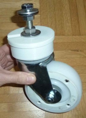
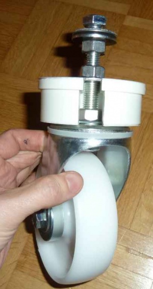
Add a rotation sensor to the free wheel to detect 'motion/no motion over ground' of the mower and thereby detecting obstacles. The sensor simulates a bumper (if no motion detected it triggers like a bumper).
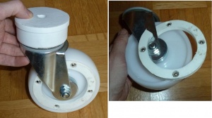
The sensor is based on a compass module (which internally measures magnetic field changes via hall sensors) and rotating magnets.
Photos
Videos
Principle test https://www.youtube.com/watch?v=SGfPwGnzHT4
Outdoor test https://www.youtube.com/watch?v=UbwwP1jQigM
Required components
- Arduino Nano (placed into printed 3D part) and powered (VIN pin) via Ardumower PCB 9V output pin
- HMC5883 compass sensor (placed into printed 3D part)
- 4 ball magnets (10mm diameter)
- printed 3D parts
Download
Note: the sensor simulates an Ardumower bumper (and will be connected to the PCB bumper pin): when no motion is detected, a bumper press is simulated. Ardumower only evaluates the bumper when in driving state.
Wiring
Arduino Nano Vin    -- Ardumower PCB 9V out
Arduino Nano GND    -- Ardumower PCB P11 GND
Arduino Nano D8     -- Ardumower PCB P11 bumper sensor input (left/right)
Arduino Nano 5v out -- HMC5883 VCC
Arduino Nano GND    -- HMC5883 GND
Arduino Nano A4     -- HMC5883 SDA
Arduino Nano A5     -- HMC5883 SCL
Forum
https://www.ardumower.de/index.php/de/forum/sensoren/1603-sensor-fuer-das-stuetzrad-free-wheel#14955


