GPS: Unterschied zwischen den Versionen
(→Visualization of GPS data) |
(→GPS error) |
||
| (5 dazwischenliegende Versionen desselben Benutzers werden nicht angezeigt) | |||
| Zeile 12: | Zeile 12: | ||
= Wiring: = | = Wiring: = | ||
| − | GPS | + | GPS VCC -- PCB VCC |
| − | GPS | + | GPS GND -- PCB GND |
| − | GPS | + | GPS TX -- PCB GPS RX |
| − | GPS | + | GPS RX -- PCB GPS TX |
= Visualization of GPS data = | = Visualization of GPS data = | ||
| − | GPS data (course, speed, position etc.) can be plotted by pfodApp | + | GPS data (course, speed, position etc.) can be plotted by pfodApp. One neat thing I discovered is that you can get precise heading and speed even when moving short distances (< 2m). This works because the GPS receiver is evaluating the signal phase due to the doppler effect. |
| + | |||
| + | hdop measurement error indication (the more satellites are from different directions, the lower the error) | ||
| + | sat number of satellites in view | ||
| + | spd ground speed m/s | ||
| + | course ground course degree | ||
| + | alt altitude meter | ||
| + | lat latitude | ||
| + | lon longitude | ||
<gallery> | <gallery> | ||
File: gpsplot.jpg | GPS plot | File: gpsplot.jpg | GPS plot | ||
| − | File: gpsplotting.jpg | GPS plot (heading/speed via doppler) | + | File: gpsplotting.jpg | GPS plot (heading/speed via doppler effect) |
File: gpstracking.jpg | GPS 2d map (tracked perimeter) | File: gpstracking.jpg | GPS 2d map (tracked perimeter) | ||
</gallery> | </gallery> | ||
= GPS error = | = GPS error = | ||
| − | Typical GPS error is 2-5 meters (at a sample rate of 1 Hz). As this is not sufficient as a replacement for a perimeter wire, GPS can only be seen as an extension or for global navigation (navigation from one lawn to another lawn) | + | Typical GPS error is 2-5 meters (at a sample rate of 1 Hz). As this is not sufficient as a replacement for a perimeter wire, GPS can only be seen as an extension or for global navigation (navigation from one lawn to another lawn). |
= Further links = | = Further links = | ||
Aktuelle Version vom 3. Juni 2016, 10:12 Uhr
Inhaltsverzeichnis
Abstract


With the help of a GPS receiver (e.g. GY-NEO6MV2, ublox 6m), the long-term position can be calculated. Therefore, the GPS position values will be averaged.
Currently, GPS is used
- to receive current date and time
Wiring:
GPS VCC -- PCB VCC
GPS GND -- PCB GND
GPS TX  -- PCB GPS RX
GPS RX  -- PCB GPS TX
Visualization of GPS data
GPS data (course, speed, position etc.) can be plotted by pfodApp. One neat thing I discovered is that you can get precise heading and speed even when moving short distances (< 2m). This works because the GPS receiver is evaluating the signal phase due to the doppler effect.
hdop    measurement error indication (the more satellites are from different directions, the lower the error)
sat     number of satellites in view
spd     ground speed m/s
course  ground course degree
alt     altitude meter
lat     latitude
lon     longitude
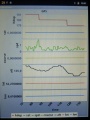
GPS plot
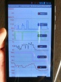
GPS plot (heading/speed via doppler effect)
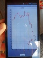
GPS 2d map (tracked perimeter)


GPS error
Typical GPS error is 2-5 meters (at a sample rate of 1 Hz). As this is not sufficient as a replacement for a perimeter wire, GPS can only be seen as an extension or for global navigation (navigation from one lawn to another lawn).