IMU: Unterschied zwischen den Versionen
(→Abstract) |
|||
| (91 dazwischenliegende Versionen von 2 Benutzern werden nicht angezeigt) | |||
| Zeile 1: | Zeile 1: | ||
=Abstract= | =Abstract= | ||
| − | + | [[File: Imu_assembly.png | 400px]] | |
| − | File: | + | |
| − | + | ||
| − | An IMU ( | + | An IMU (Intertia Measurement Unit) is a key component of an inertia navigation system. We use it to: |
*detect if the robot is in tilt orientation | *detect if the robot is in tilt orientation | ||
*keep the robot on track for the 'lane-by-lane' mowing pattern | *keep the robot on track for the 'lane-by-lane' mowing pattern | ||
| + | [[File: Slope1.png | 400px]] | ||
=Acceleration sensor= | =Acceleration sensor= | ||
An acceleration sensor measures earth gravity force (m*s^2) in all 3 robot axes (x/y/z) allowing you to calculate the orientation towards earth center of the robot (Roll, Pitch). However, it cannot detect movement around Yaw - this requires a gyro. | An acceleration sensor measures earth gravity force (m*s^2) in all 3 robot axes (x/y/z) allowing you to calculate the orientation towards earth center of the robot (Roll, Pitch). However, it cannot detect movement around Yaw - this requires a gyro. | ||
| − | + | [[File: Ardumower_pitch_roll_yaw.png|400px]] | |
| − | File: Ardumower_pitch_roll_yaw.png | + | |
| − | + | ||
=Gyro= | =Gyro= | ||
| − | A gyro | + | A gyro measures rotational speed (degree/second) in all 3 robot axes (Roll, Pitch, Yaw). This allows us to correct the robot if it is driving 'off-course' due to wet conditions or slope. When integrating (adding) gyro values over time, the actual course (yaw) can be calculated. However, because each sensor reading has a small error, the course will 'drift' over time. This needs to be corrected via an absolute heading sensor (compass). |
| + | |||
| + | Typical gyro measurement errors: | ||
| + | |||
| + | noise dps/sqrt(Hz) | ||
| + | L3G4200D 0.03 | ||
| + | ITG3200 0.03 | ||
| + | L3GD20 0.03 | ||
| + | BMG160/BNO055 0.014 | ||
| + | MPU9250 0.01 | ||
| + | L3GD20H 0.011 | ||
| + | LSM9DS0 0.00875 | ||
| + | BMI160 0.007 | ||
| + | MAX21003 0.007 | ||
| + | L2G2IS/L2G3IS 0.006 | ||
| + | MPU9150/MPU6050 0.005 | ||
| + | ADXRS290 0.004 | ||
| + | CRM100/200 0.003 | ||
| + | GYPRO2300 0.00277 | ||
=Compass= | =Compass= | ||
| − | If a robot drives on a wet lawn, you'll notice quickly that it will not drive straight forward, but instead tends to drive into the direction of the slope. | + | If a robot drives on a wet lawn, you'll notice quickly that it will not drive straight forward, but instead tends to drive into the direction of the slope. Reading a compass heading can solve this problem and the robot will drive straight forward again . |
| + | |||
| + | However, a compass has two problems: | ||
| + | |||
| + | # If tilting the robot, the compass measurements (x,y,z) relate to the tilted robot. So, you need to correct them using knowing the tilt angles. This requires the use of the accerlation sensor (x,y). | ||
| + | # The compass measurements are influenced by motors. So you may need to switch of the motor to get an accurate measurement. | ||
| + | |||
| + | Typical compass measurement errors: | ||
| − | + | sensitivity (uT) typical heading error (degree) | |
| + | AK8975 (MPU9150) 0.3 5 | ||
| + | BNO055 0.3 2.5 | ||
| + | CMPS11 (9S0 2413 530BS) 2.0 | ||
| + | HMC5883L (GY-80) 0.2 1.5 | ||
| + | AK8963 (MPU9250) 0.15 not tested | ||
| + | LIS3MDL 0.14 not tested | ||
| + | LSM303DLM | ||
| + | MAG3110/FXOS8700CQ 0.1 not tested | ||
=Sensor fusion= | =Sensor fusion= | ||
| Zeile 27: | Zeile 57: | ||
We use a complementary filter to fusion all sensor values. | We use a complementary filter to fusion all sensor values. | ||
| + | |||
| + | [[File: Ardumower_sensor_fusion.png | 600px]] | ||
| + | |||
| + | =IMU module= | ||
<gallery> | <gallery> | ||
| − | File: | + | File: Gy80.jpg | GY-80 module |
| + | File: GY80-Schematic.jpg | GY-80 schematics | ||
</gallery> | </gallery> | ||
| − | + | GY-80 | |
*Acceleration sensor: ADXL345B | *Acceleration sensor: ADXL345B | ||
*Compass sensor: HMC5883L | *Compass sensor: HMC5883L | ||
*Gyro: L3G4200D | *Gyro: L3G4200D | ||
*Pressure sensor: BMP085 (not used here) | *Pressure sensor: BMP085 (not used here) | ||
| − | |||
| − | |||
| − | |||
| − | |||
| − | |||
=Assembly= | =Assembly= | ||
| − | This photo shows how the IMU module is placed in driving position (the | + | This photo shows how the IMU module is placed in the driving position (the red arrow shows the driving position). Ensure a minimum distance of 30cm from all motors. This minimum distance seems to be needed to ensure the compass is not disturbed by dynamically disturbing sources (like motors). |
| − | + | [[File: Imu_assembly.png | 400px]] | |
| − | File: | + | |
| − | + | ||
=Calibration abstract= | =Calibration abstract= | ||
This one-time calibration ensures that: | This one-time calibration ensures that: | ||
| − | *All 3 axes measurements of the acceleration sensor are weighted equally. This calibration can be performed | + | *All 3 axes measurements of the acceleration sensor are weighted equally. This calibration can even be performed externally to the robot. |
| − | * | + | *Cables, metal, etc. which are located in the robot near the IMU module have no effect on the compass data. |
Why is it needed? | Why is it needed? | ||
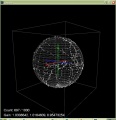
| − | + | The origin of a 3D compass point is 0,0,0 (x,y,z) and points to the north pole. If the 3D compass is rotated around all of its axes i.e. all values of x, y and z are measured then these points will lie on a sphere. | |
| − | + | [[File: Compass_sphere.png |400px]] | |
| − | File: Compass_sphere.png | + | |
| − | + | ||
If you add a magnetic material (e.g. metal) near the compass, the measured values from the origin (0,0,0) of the sensor suddenly point in one direction only - Why? | If you add a magnetic material (e.g. metal) near the compass, the measured values from the origin (0,0,0) of the sensor suddenly point in one direction only - Why? | ||
| Zeile 71: | Zeile 97: | ||
<gallery> | <gallery> | ||
| − | File: Compass_ellipsoid.jpg | + | File: Compass_ellipsoid.jpg | Uncalibrated readings do not lie on a sphere but on an ellipsoid and have shifted from the origin of the sensor |
| − | File: Compass_ellipsoid_cal1.jpg | + | File: Compass_ellipsoid_cal1.jpg | Shift-corrected values |
| − | File: Compass_ellipsoid_cal2.jpg | + | File: Compass_ellipsoid_cal2.jpg | Calibrated values are now reformed (or undeformed) again on a sphere, centered around the origin of the sensor |
</gallery> | </gallery> | ||
| − | + | The goal of the calibration is that the measurements are centered again on a sphere around the origin of the sensor. | |
| − | + | ||
| − | + | ||
| − | + | ||
| − | + | ||
| − | + | ||
| − | + | ||
| − | + | ||
| − | + | ||
| − | + | ||
| − | + | ||
| − | + | ||
| − | + | ||
| − | + | ||
| − | + | ||
| − | + | ||
| − | + | ||
| − | + | ||
| − | + | ||
| − | + | ||
| − | + | ||
| − | + | ||
| − | + | ||
| − | + | ||
| − | + | ||
| − | + | ||
| − | + | ||
| − | + | ||
| − | + | ||
| − | + | ||
| − | + | ||
| − | + | ||
| − | + | ||
| − | + | ||
| − | + | ||
| − | + | ||
| − | + | ||
| − | + | ||
| − | + | ||
| − | + | ||
| − | + | ||
| − | + | ||
| − | + | ||
| − | + | ||
| − | + | ||
| − | + | ||
| − | + | ||
| − | + | ||
| − | + | ||
| − | + | ||
| − | + | ||
| − | + | ||
| − | + | ||
| − | + | ||
| − | =Calibration | + | =Calibration steps= |
==Acceleration sensor== | ==Acceleration sensor== | ||
| − | Place each of the 6 module sides exactly upright, do not move and choose 'next side calibration': | + | This calibration can be performed outside of the robot. Place each of the 6 module sides exactly upright, do not move and choose 'next side calibration': |
*Via serial console "IMU acc calibration next side" OR | *Via serial console "IMU acc calibration next side" OR | ||
| Zeile 143: | Zeile 116: | ||
Repeat this step for all 6 sides. After all 6 sides are calibrated, you will hear a short melody. | Repeat this step for all 6 sides. After all 6 sides are calibrated, you will hear a short melody. | ||
| − | + | [[File: Gy80_acc_calibration.png|500px]] | |
| − | File: Gy80_acc_calibration.png | + | |
| − | + | ||
==Compass sensor== | ==Compass sensor== | ||
| − | + | This calibration can only be performed inside of the robot (IMU in its final position). Start the compass calibration: | |
*Via serial console "IMU com calibration start/stop" OR | *Via serial console "IMU com calibration start/stop" OR | ||
| Zeile 155: | Zeile 126: | ||
Hold each of the 6 module sides to North direction and tilt the module until minimum and maximum of the axis does not change anymore (until no tone is outputted anymore): | Hold each of the 6 module sides to North direction and tilt the module until minimum and maximum of the axis does not change anymore (until no tone is outputted anymore): | ||
| − | + | [[File: Gy80_com_calibration.png|500px]] | |
| − | File: Gy80_com_calibration.png | + | |
| − | + | ||
| − | =Calibration test= | + | ==Calibration quality test== |
| − | For | + | For a quality test, you can plot the calibration results (Yaw, Pitch, Roll) via pfodApp. Place the robot on a flat ground and let it rotate (pfodApp: click on "Commands->Auto rotate" until robot rotates). Alternatively, you can let the robot drive a circle (pfodApp: click "Manual->Right" until it drives the desired radius). Finally, choose 'Plot->IMU' to see the calibration result. |
| − | + | For the yaw plot, the curve should be a straight line when the robot is rotating with a constant speed. | |
| − | + | ||
| − | + | ||
| − | + | [[File: Ardumower_imu_plotting.jpg|300px]] | |
| − | + | ||
| − | + | ||
| − | + | ||
| − | + | ||
| − | + | ||
| − | + | ||
| − | + | ||
| − | + | ||
| − | + | ||
| − | + | ||
| − | + | ||
| − | + | ||
| − | + | ||
| − | + | ||
| − | + | ||
| − | + | ||
| − | + | ||
| − | + | ||
| − | + | ||
| − | File: Ardumower_imu_plotting.jpg | + | |
| − | + | ||
=Videos= | =Videos= | ||
Aktuelle Version vom 11. Mai 2017, 11:11 Uhr
Inhaltsverzeichnis
Abstract

An IMU (Intertia Measurement Unit) is a key component of an inertia navigation system. We use it to:
- detect if the robot is in tilt orientation
- keep the robot on track for the 'lane-by-lane' mowing pattern

Acceleration sensor
An acceleration sensor measures earth gravity force (m*s^2) in all 3 robot axes (x/y/z) allowing you to calculate the orientation towards earth center of the robot (Roll, Pitch). However, it cannot detect movement around Yaw - this requires a gyro.

Gyro
A gyro measures rotational speed (degree/second) in all 3 robot axes (Roll, Pitch, Yaw). This allows us to correct the robot if it is driving 'off-course' due to wet conditions or slope. When integrating (adding) gyro values over time, the actual course (yaw) can be calculated. However, because each sensor reading has a small error, the course will 'drift' over time. This needs to be corrected via an absolute heading sensor (compass).
Typical gyro measurement errors:
                noise dps/sqrt(Hz)
L3G4200D        0.03
ITG3200         0.03
L3GD20          0.03
BMG160/BNO055   0.014
MPU9250         0.01
L3GD20H         0.011
LSM9DS0         0.00875
BMI160          0.007
MAX21003        0.007
L2G2IS/L2G3IS   0.006
MPU9150/MPU6050 0.005
ADXRS290        0.004
CRM100/200      0.003
GYPRO2300       0.00277
Compass
If a robot drives on a wet lawn, you'll notice quickly that it will not drive straight forward, but instead tends to drive into the direction of the slope. Reading a compass heading can solve this problem and the robot will drive straight forward again .
However, a compass has two problems:
- If tilting the robot, the compass measurements (x,y,z) relate to the tilted robot. So, you need to correct them using knowing the tilt angles. This requires the use of the accerlation sensor (x,y).
- The compass measurements are influenced by motors. So you may need to switch of the motor to get an accurate measurement.
Typical compass measurement errors:
                        sensitivity (uT)       typical heading error (degree)
AK8975 (MPU9150)        0.3                    5
BNO055                  0.3                    2.5
CMPS11 (9S0 2413 530BS)                        2.0
HMC5883L (GY-80)        0.2                    1.5
AK8963 (MPU9250)        0.15                   not tested
LIS3MDL                 0.14                   not tested
LSM303DLM
MAG3110/FXOS8700CQ      0.1                    not tested
Sensor fusion
To eliminate the issues of all sensor, they are merged to compute the course (degree) and pitch/roll angles.
We use a complementary filter to fusion all sensor values.

IMU module
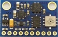
GY-80 module
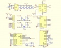
GY-80 schematics


GY-80
- Acceleration sensor: ADXL345B
- Compass sensor: HMC5883L
- Gyro: L3G4200D
- Pressure sensor: BMP085 (not used here)
Assembly
This photo shows how the IMU module is placed in the driving position (the red arrow shows the driving position). Ensure a minimum distance of 30cm from all motors. This minimum distance seems to be needed to ensure the compass is not disturbed by dynamically disturbing sources (like motors).
Calibration abstract
This one-time calibration ensures that:
- All 3 axes measurements of the acceleration sensor are weighted equally. This calibration can even be performed externally to the robot.
- Cables, metal, etc. which are located in the robot near the IMU module have no effect on the compass data.
Why is it needed? The origin of a 3D compass point is 0,0,0 (x,y,z) and points to the north pole. If the 3D compass is rotated around all of its axes i.e. all values of x, y and z are measured then these points will lie on a sphere.

If you add a magnetic material (e.g. metal) near the compass, the measured values from the origin (0,0,0) of the sensor suddenly point in one direction only - Why? There are two types of disturbances of the magnetic field which change / move the values:
- Hard ircon (e.g. magnets): the sphere moves
- Soft ircon (e.g. metal): the sphere deforms (becomes an Ellipsoid)
Example measurements
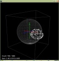
Uncalibrated readings do not lie on a sphere but on an ellipsoid and have shifted from the origin of the sensor
Shift-corrected values
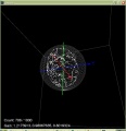
Calibrated values are now reformed (or undeformed) again on a sphere, centered around the origin of the sensor


The goal of the calibration is that the measurements are centered again on a sphere around the origin of the sensor.
Calibration steps
Acceleration sensor
This calibration can be performed outside of the robot. Place each of the 6 module sides exactly upright, do not move and choose 'next side calibration':
- Via serial console "IMU acc calibration next side" OR
- Via pfodApp "Settings->IMU->acc calibration next side"
Do not move the module during the measurement of each side! During measurement you will hear a short beep tone.
Repeat this step for all 6 sides. After all 6 sides are calibrated, you will hear a short melody.

Compass sensor
This calibration can only be performed inside of the robot (IMU in its final position). Start the compass calibration:
- Via serial console "IMU com calibration start/stop" OR
- Via pfodApp "Settings->IMU->com calibration start/stop"
Hold each of the 6 module sides to North direction and tilt the module until minimum and maximum of the axis does not change anymore (until no tone is outputted anymore):

Calibration quality test
For a quality test, you can plot the calibration results (Yaw, Pitch, Roll) via pfodApp. Place the robot on a flat ground and let it rotate (pfodApp: click on "Commands->Auto rotate" until robot rotates). Alternatively, you can let the robot drive a circle (pfodApp: click "Manual->Right" until it drives the desired radius). Finally, choose 'Plot->IMU' to see the calibration result.
For the yaw plot, the curve should be a straight line when the robot is rotating with a constant speed.

Videos