IMU: Unterschied zwischen den Versionen
(→Calibration test) |
(→Abstract) |
||
| Zeile 1: | Zeile 1: | ||
=Abstract= | =Abstract= | ||
| + | [[File:Imu.jpg]] | ||
| + | |||
An IMU (Intertial Measurement Unit) is key component of an intertial navigation system. We use it to: | An IMU (Intertial Measurement Unit) is key component of an intertial navigation system. We use it to: | ||
*detect if the robot is in tilt orientation | *detect if the robot is in tilt orientation | ||
Version vom 13. September 2014, 12:47 Uhr
Inhaltsverzeichnis
Abstract
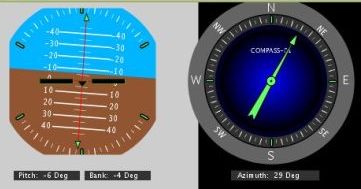
An IMU (Intertial Measurement Unit) is key component of an intertial navigation system. We use it to:
- detect if the robot is in tilt orientation
- keep the robot on track for the 'lane-by-lane' mowing pattern
Acceleration sensor
An acceleration sensor measures earth gravity force (m*s^2) in all 3 robot axes (x/y/z) allowing you to calculate the orientation towards earth center of the robot (Roll, Pitch). However, it cannot detect movement around Yaw - this requires a gyro.
Gyro
A gyro measure rotation speed (degree/second) in all 3 robot axes (Rol, Pitch, Yaw). This allows us to correct the robot if it is driving 'off-course' due to wet conditions or slope.
Compass
If a robot drives on a wet lawn, you'll notice quickly that it will not drive straight forward, but instead tends to drive into the direction of the slope. A compass can solve this problem and the robot will drive again straight forward.
However, a compass has a problem: if tilting the robot, the compass measurements (x,y,z) relate to the tilted robot. So, you need to correct them using knowing the tilt angles. This requires the use of the accerlation sensor (x,y).
Sensor fusion
To eliminate the issues of all sensor, they are merged to compute the course (degree) and pitch/roll angles.
We use a complementary filter to fusion all sensor values.
IMU module GY-80
- Acceleration sensor: ADXL345B
- Compass sensor: HMC5883L
- Gyro: L3G4200D
- Pressure sensor: BMP085 (not used here)
Assembly
This photo shows how the IMU module is placed in driving position (the black arrow shows the driving position). The shown tube was a prototype. Actually, you can now place the IMU module directly in the robot.
Calibration abstract
This one-time calibration ensures that:
- All 3 axes measurements of the acceleration sensor are weighted equally. This calibration can be performed even outside of the robot.
- Cable, metal, etc. which is located in the robot near the IMU module has no effect on the compass data.
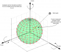
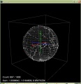
Why is it needed? A measured value (x, y, z) of a 3D compass points (as seen by his origin 0,0,0) always in one direction: to the north pole. If you rotate the 3D compass around all of its axes, all measured values lie on a sphere:
If you add a magnetic material (e.g. metal) near the compass, the measured values from the origin (0,0,0) of the sensor suddenly point in one direction only - Why? There are two types of disturbances of the magnetic field which change / move the values:
- Hard ircon (e.g. magnets): the sphere moves
- Soft ircon (e.g. metal): the sphere deforms (becomes an Ellipsoid)
Example measurements
Calibration (v0.9.3)
Acceleration sensor
This one-time calibration ensures that all 3 axes measurements are weighted equally. This calibration can be performed even outside of the robot.
1. Connect the Arduino Nano to your PC. On the PC, open the serial console (19200) in the Arduino environment. After the automatic gyro calibration menu appears (this can be shown at any time by pressing the "m" + ENTER keys).
2. Start the calibration by pressing "1" + ENTER keys.
2.1. After calibration, each of the 6 sides of the module has to look up-side and down-side (rotated 180 °). The module has 6 sides, so it must be rotated 6 times, so that each side once is on the table (you can hold the module with your hand without moving it). Press ENTER after each calibration step. The aim of the calibration to determine the acceleration due to gravity (more precisely, the minimum / maximum value) for each axis . The module must not be artificially accelerated. The order of the sides does not matter.
Finally, the calibration values for acceleration sensor are printed out on serial console.
Compass sensor
First ensure that the IMU module is mounted on the final position and that entire robotic electronic equipment and metal objects are 30cm or more away from it (ie the sensor is not distracted by metallic objects in its environment).
1. Download ArduMag calibration app for Android. 2. If not done yet, pair your Android device with the Bluetooth module: On the Android device main screen, choose symbol "Settings" (via Android menu). Now choose "Wirless and Networks->Bluetooth Settings" and "Find device". Finally, choose "pair with this device" and enter your pin (very often "1234"). The Bluetooth module should now appear as "paired". 3. In the ArduMag app, press the Android menu key and then "Bluetooth" to connect with your Bluetooth module (and your robot). The robot should confirm the connection with a beep. The number of measurements should increase.
Turn around the robot slowly for all axes and all 6 sides for at least 360 degrees:
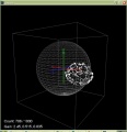
The order of the axis of rotation and the direction does not matter. For example, rotate each side 180 degree clockwise and then again 180 degree counterclockwise (result is a 360 degree rotation). The measurements may not fit a sphere. Examples:
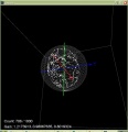
Finally, press 'Calibrate' to finish the calibration. The robot will confirm the calibration with two beeps. The measurements should fit a sphere now. Examples:
Calibration (SVN version)
Acceleration sensor
Place each of the 6 module sides exactly upright, do not move and choose 'next side calibration':
- Via serial console "IMU acc calibration next side" OR
- Via pfodApp "Settings->IMU->acc calibration next side"
Do not move the module during the measurement of each side! During measurement you will hear a short beep tone.
Repeat this step for all 6 sides. After all 6 sides are calibrated, you will hear a short melody.
Compass sensor
Make sure the module is far away from magnetic fields or ferreous sources! Start the compass calibration:
- Via serial console "IMU com calibration start/stop" OR
- Via pfodApp "Settings->IMU->com calibration start/stop"
Hold each of the 6 module sides to North direction and tilt the module until minimum and maximum of the axis does not change anymore (until no tone is outputted anymore):
Calibration test
For testing calibration, hold module (parts upside) against a table edge and do not move. Write down the Yaw-value (example: -95,45). Then rotate the module by 180 degree and hold it again against the table edge. Now the Yaw-value should output 180 degree away (example: -95,45 + 180 = 84,55). Repeat this test for both remaining sides of the module.
... hold module against a table edge ...
calls=30    yaw=-95.56    pitch=0.02    roll=2.52    com=-95.91    com180=84.09    gyroZ=0.00
calls=30    yaw=-95.48    pitch=-0.11    roll=2.33    com=-95.81    com180=84.19    gyroZ=-0.01
calls=30    yaw=-95.42    pitch=0.03    roll=2.42    com=-95.65    com180=84.35    gyroZ=-0.00
calls=30    yaw=-95.45    pitch=-0.21    roll=2.38    com=-95.35    com180=84.65    gyroZ=-0.00
... turn 180 degree, hold again against table edge ...
calls=30    yaw=85.06    pitch=-2.50    roll=0.04    com=84.91    com180=-95.09    gyroZ=-0.03
calls=30    yaw=84.90    pitch=-2.59    roll=0.05    com=84.63    com180=-95.37    gyroZ=-0.02
calls=30    yaw=85.19    pitch=-2.55    roll=0.01    com=84.73    com180=-95.27    gyroZ=-0.01
calls=30    yaw=84.98    pitch=-2.73    roll=0.02    com=84.85    com180=-95.15    gyroZ=-0.01
If deviation is more than one degree, repeat calibration steps!
You can plot the calibration results (Yaw, Pitch, Roll) via pfodApp too:
