Inertialsensor - IMU
Inhaltsverzeichnis
Zusammenfassung

Ein Modul namens IMU (Intertia Measurement Unit) ist das Herzstück eines Trägheitsnavigationssystems, mit dem wir folgendes erreichen können:
- feststellen, ob der Ardumower umgekippt ist (Neigungswinkel)
- regeln einer exakten Geradeausfahrt z.B: für das Mähen in parallelen Bahnen
Beschleunigungssensor
Dieser Sensor mißt die translatorischen und rotatorischen Beschleunigungswerte des Ardumower bezüglich der 3 Raumachsen (x/y/z). Die Auswertung dieser Signale ermöglicht dem Ardumower die Berechnung der räumlichen Bewegung und der Veränderung der räumlichen Position. Zur Bestimmung der Raumwinkeländerungen beinhaltet die IMU ein Gyromodul.

Gyro
Ein Gyro mißt die Rotationsgeschwindigkeit (Winkelgrad/Sekunde) um alle 3 Roboterachsen (Roll, Pitch, Yaw). Das ermöglicht die Kurskorrektur wenn der Roboter durch z.B. nässebedingten Schlupf der Räder außer Kurs gerät. When integrating (adding) gyro values over time, the actual course (yaw) can be calculated. However, because each sensor reading has a small error, the course will 'drift' over time. This needs to be corrected via an absolute heading sensor (compass).
Typical gyro measurement errors:
                noise dps/sqrt(Hz)
L3G4200D        0.03
BMG160/BNO055   0.014
MPU9150         0.005
Compass
Fährt der Roboter auf nassem Gras, wird man feststellen, dass er nicht genau geradeaus fährt, sondern in Richtung des Rades tendiert, an dem Schlupf auftritt. Unter Auswertung eines Kompasssignals kann dieses Problem gelöst werden und der Robbi wird wieder geradeausfahren.
Ein Kompass hat jedoch 2 Probleme:
- If tilting the robot, the compass measurements (x,y,z) relate to the tilted robot. So, you need to correct them using knowing the tilt angles. This requires the use of the accerlation sensor (x,y).
- The compass measurements are influenced by motors. So you may need to switch of the motor to get an accurate measurement.
Sensor fusion
To eliminate the issues of all sensor, they are merged to compute the course (degree) and pitch/roll angles.
We use a complementary filter to fusion all sensor values.
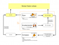
IMU sensor fusion

Additionally, gyro/acceleration and compass sensors can be further input to a position estimation.
IMU modules
GY-80
- Acceleration sensor: ADXL345B
- Compass sensor: HMC5883L
- Gyro: L3G4200D
- Pressure sensor: BMP085 (not used here)
MPU9150
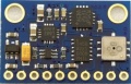
GY-80 module
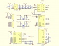
GY-80 schematics
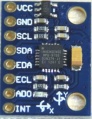
MPU9150 module (in development/testing)


Assembly
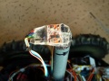
This photo shows how the IMU module is placed in the driving position (the black arrow shows the driving position). The tube shown was needed to ensure a minimum distance of 30cm from all motors. This minimum distance seems to be needed to ensure the compass is not disturbed by dynamically disturbing sources (like motors).
GY-80 assembly

Calibration abstract
This one-time calibration ensures that:
- All 3 axes measurements of the acceleration sensor are weighted equally. This calibration can even be performed externally to the robot.
- Cables, metal, etc. which are located in the robot near the IMU module have no effect on the compass data.
Why is it needed? The origin of a 3D compass point is 0,0,0 (x,y,z) and points to the north pole. If the 3D compass is rotated around all of its axes i.e. all values of x, y and z are measured then these points will lie on a sphere.

If you add a magnetic material (e.g. metal) near the compass, the measured values from the origin (0,0,0) of the sensor suddenly point in one direction only - Why? There are two types of disturbances of the magnetic field which change / move the values:
- Hard ircon (e.g. magnets): the sphere moves
- Soft ircon (e.g. metal): the sphere deforms (becomes an Ellipsoid)
Example measurements
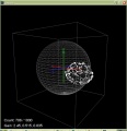
Uncalibrated readings do not lie on a sphere but on an ellipsoid and have shifted from the origin of the sensor
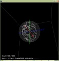
Shift-corrected values
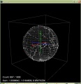
Calibrated values are now reformed (or undeformed) again on a sphere, centered around the origin of the sensor


The goal of the calibration is that the measurements are centered again on a sphere around the origin of the sensor.
Abgleich (letzte Version)
Acceleration sensor
This calibration can be performed outside of the robot. Place each of the 6 module sides exactly upright, do not move and choose 'next side calibration':
- Via serial console "IMU acc calibration next side" OR
- Via pfodApp "Settings->IMU->acc calibration next side"
Do not move the module during the measurement of each side! During measurement you will hear a short beep tone.
Repeat this step for all 6 sides. After all 6 sides are calibrated, you will hear a short melody.
Compass sensor
This calibration can be performed outside or inside of the robot (in its final position). Make sure the module is far away from magnetic fields or ferreous sources! Start the compass calibration:
- Via serial console "IMU com calibration start/stop" OR
- Via pfodApp "Settings->IMU->com calibration start/stop"
Hold each of the 6 module sides to North direction and tilt the module until minimum and maximum of the axis does not change anymore (until no tone is outputted anymore):
Calibration quality test
Table test
For testing calibration quality, hold module (parts upside) against a table edge and do not move. Write down the Yaw-value (example: -95,45). Then rotate the module by 180 degree and hold it again against the table edge. Now the Yaw-value should output 180 degree away (example: -95,45 + 180 = 84,55). Repeat this test for both remaining sides of the module.
... hold module against a table edge ...
calls=30    yaw=-95.56    pitch=0.02    roll=2.52    com=-95.91    com180=84.09    gyroZ=0.00
calls=30    yaw=-95.48    pitch=-0.11    roll=2.33    com=-95.81    com180=84.19    gyroZ=-0.01
calls=30    yaw=-95.42    pitch=0.03    roll=2.42    com=-95.65    com180=84.35    gyroZ=-0.00
calls=30    yaw=-95.45    pitch=-0.21    roll=2.38    com=-95.35    com180=84.65    gyroZ=-0.00
... turn 180 degree, hold again against table edge ...
calls=30    yaw=85.06    pitch=-2.50    roll=0.04    com=84.91    com180=-95.09    gyroZ=-0.03
calls=30    yaw=84.90    pitch=-2.59    roll=0.05    com=84.63    com180=-95.37    gyroZ=-0.02
calls=30    yaw=85.19    pitch=-2.55    roll=0.01    com=84.73    com180=-95.27    gyroZ=-0.01
calls=30    yaw=84.98    pitch=-2.73    roll=0.02    com=84.85    com180=-95.15    gyroZ=-0.01
If deviation is more than one degree, repeat calibration steps!
pfodApp test
For a more detailed quality test, you can plot the calibration results (Yaw, Pitch, Roll) via pfodApp. Place the robot on a flat ground and let it rotate (pfodApp: click on "Commands->Auto rotate" until robot rotates). Alternatively, you can let the robot drive a circle (pfodApp: click "Manual->Right" until it drives the desired radius). Finally, choose 'Plot->IMU' to see the calibration result.
For the yaw plot, the curve should be a straight line when the robot is rotating with a constant speed.


Videos