Motor-Treiber: Unterschied zwischen den Versionen
(Die Seite wurde neu angelegt: „= Abstract = Ardumower's design uses two different types of motors (all motors can be purchased via the [https://www.marotronics.de/index.php?k=7 shop] File:…“) |
(→Protector PCB) |
||
| (103 dazwischenliegende Versionen von 2 Benutzern werden nicht angezeigt) | |||
| Zeile 1: | Zeile 1: | ||
| − | = | + | = Zusammenfassung = |
| − | Ardumower | + | Das Ardumower- Design verwendet zwei verschiedene Typen von Motoren. Alle Motoren können im [https://www.marotronics.de/index.php?k=7 Shop] [[File: shopping.png|link=https://www.marotronics.de/index.php?k=7]]) erworben werden: |
| − | * | + | * Zwei Getriebemotoren als Antriebe (Radmotoren) mit eingebautem Encoder (für Weg- und Geschwindigkeitssteuerung) |
| − | * | + | * einen Motor (mit hoher Drehzahl) zum Mähen (Mähmotor) |
| − | + | Zur Steuerung der Motoren sind Motortreiber erforderlich. Desweiteren messen wir den Motorstrom mit dem Motortreiber. Dies erlaubt uns, Hindernisse zu detektieren, da der Motorstrom bei Hindernissen ansteigt. Ardumower verwendet zwei Dual MC33926 Motortreiber. Zwei Kanäle für linker und rechter Motor und zwei Kanäle (parallel geschaltet) für den Mähmotor. | |
| − | + | Es ist nicht empfehlenswert die Motoren direkt an die Motortreiber anzuschliessen, da gerade beim schnellen Wechsel von Vor- und Rückwärtsfahren (bzw. umgekehrt) hohe Spannungsspitzen auftreten und diese können die Motortreiber auf lange Sicht bestädigen. Daher verwenden wir ein Protector Board zwischen Motortreiber und Motoren. | |
| − | + | ||
| − | + | [[File:Ardumower_motordriver_overview.png|800px]] | |
| − | + | = Spannungen = | |
| + | Der Ardumower verwendet wie alle modernen Systeme 24V Motoren. | ||
| − | |||
| − | + | = Bauanleitung Motortreiber (MC33926) = | |
| − | + | ||
| − | + | ||
| − | + | Eigenschaften des Motortreibers: bis zu 3A, mit integriertem Stromsensor und Thermoschutz | |
| − | |||
<gallery> | <gallery> | ||
| − | + | File: Ardumower_motordriver_overview.png | PCB, MC33926, protector and motors | |
| − | + | File: Pcb_mc33926.jpg | PCB und MC33926 | |
| − | + | File:Mc33926.jpg | Pin-Belegung | |
| + | File:MC33926_schematics.jpg | Schaltbild MC33926 | ||
</gallery> | </gallery> | ||
| − | |||
| − | + | Hier findest Du eine Anleitung wie der Motortreiber auf das PCB gesetzt wird. | |
| − | * | + | * [https://www.youtube.com/watch?feature=player_embedded&v=DokrJiVzX2I Video-Anleitung: Dual MC33926] |
| − | + | Für Verkabelung von Motortreiber, Protector PCB und Motoren bitte die Anleitung im Abschnitt "Protector PCB" öffnen. | |
| − | + | ||
| − | + | ||
| − | + | ||
| − | + | ||
| − | = | + | =Protector PCB= |
| − | + | ||
| − | + | [[File:warning.png]] Protektorboard: Bei 24V Systemen kommt es zu Spannungsspitzen, die den Motortreiber schnell zerstören können. Daher wurde das Protektorboard entwickelt um dies zu verhindern. Es werden 2 Stück benötigt. Einen für die Antriebsräder und einen für den Mähmotor. Schaden kann das Protektorboard auf keinen Fall. | |
| − | + | ||
| − | + | ||
| − | + | ||
| − | + | ||
| − | + | ||
| − | + | ||
| − | + | ||
| − | + | ||
| − | + | ||
<gallery> | <gallery> | ||
| − | File: | + | File: Ardumower_motordriver_overview.png | PCB, MC33926, protector and motors |
| + | File:Protector_pcb2.jpg | Protector PCB | ||
| + | File:Protector_wiring.png | Protector PCB Verdrahtung | ||
| + | File:driver_hw_protection.png | Protector PCB Schaltbild | ||
</gallery> | </gallery> | ||
| − | + | * [https://github.com/Ardumower/ardumower/blob/master/Dokumentation/Protector%20Board/WORKSHOP%20Protector-Board.pdf Bauanleitung Protector board (empfohlen für sicheren Betrieb der Motortreiber!)] | |
| − | + | ||
| + | = Anschluss Radmotoren = | ||
<gallery> | <gallery> | ||
| − | File: | + | File: Ardumower_motordriver_overview.png | PCB, MC33926, protector and motors |
| − | File: | + | File: ardumower_motor.jpg | Ardumower Getriebemotor(Welle: 8mm Durchmesser, 5900 U/min, 0.055 Nm, Übersetzung: 1:212, Ausgangs-Drehmoment 2.45Nm, Ausgangsdrehzahl 31 U/min) |
| − | File: | + | File: magnetic_encoder.PNG | Motor wiring |
| − | File: | + | File: wheel_motor_diagram.png | Ardumower Getriebemotor Kennlinie (nur Motor) |
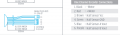
| − | File: | + | File: Ardumower_gearbox.png | Getriebe-Spezifikation |
</gallery> | </gallery> | ||
| + | Die beiden Getriebemotoren werden unabhängig voneinander gesteuert ('Differentialantrieb') : | ||
| − | + | * Fahren vorwärts/rückwärts | |
| − | + | * Lenken links/rechts | |
| − | + | Die Eigenschaften der Ardumower - Radmotoren: | |
| + | * Eine Drehzahl bis zu 31 U/min erlaubt es, den Roboter mit einer ausreichenden Geschwindigkeit von bis zu (Meter/sec = 31rpm/60 * PI * 0.25m = 0.4m/sec) bei Verwendung von Rädern mit 250 mm Durchmesser, zu bewegen. | ||
| + | * ein hohes Drehmoment (2.45 Nm) garantiert, dass der Roboter kleinere Hügel erklimmen kann (mit 2 Motoren, 250 mm Rädern, 31 U/min = 0.4m/s, Beschleunigung = 0.2 ( 1/2 der Nominalgeschwindigkeit) [http://www.robotshop.com/blog/en/drive-motor-sizing-tool-9698 see calculator] | ||
| + | * Der eingebaute Encoder kann die Drehzahl messen, die Geschwindigkeit und den Weg feststellen. | ||
| + | * 24V (Laststrom ca. 1A) | ||
| − | + | Der linke Getriebe-Motor wird wie folgt an das Protector Board angeschlossen: | |
| − | + | ||
| − | + | ||
| − | + | ||
| − | + | ||
| − | + | ||
| − | + | ||
| − | + | ||
| − | + | Motor Anschluss (linker Motor): | |
| − | + | Motor (black) ==== Protector board Motor_1_OUT(1) | |
| − | + | Motor (red) ==== Protector board Motor_1_OUT(2) | |
| − | + | ||
| − | + | ||
| − | + | ||
| − | + | ||
| − | + | ||
| − | + | ||
| − | + | ||
| − | + | ||
| − | + | ||
| − | + | ||
| − | + | ||
| − | + | ||
| − | + | ||
| − | + | Für den rechten Motor entsprechend an Protector board Motor_2_OUT(1,2) anschliessen. | |
| − | + | ||
| − | + | ||
| − | + | ||
| − | + | ||
| − | + | = Anschluss Odometrie der Getriebemotoren = | |
| − | + | Der im Ardumower-Getriebe-Motor eingebaute Encoder hilft dem Ardumower die Drehzahl bzw. zurückgelegte Distanz zu ermitteln. Hier siehst Du wie die Odometrie der Motoren an das PCB angeschlossen wird. | |
| − | + | ||
| − | + | ||
| − | + | ||
| − | + | ||
| − | + | ||
| − | + | ||
| − | + | ||
| − | + | ||
| − | + | ||
| − | + | ||
| − | + | ||
| − | + | ||
| − | + | ||
| − | + | ||
| − | + | ||
| − | + | ||
| − | + | ||
| − | + | ||
| − | + | ||
| − | + | ||
| − | + | ||
| − | + | ||
| − | + | ||
| − | + | ||
| − | + | ||
| − | + | ||
| − | + | ||
| − | + | ||
| − | + | ||
| − | + | ||
<gallery> | <gallery> | ||
| − | File: | + | File: magnetic_encoder.PNG | Motor wiring |
| + | File: ardumower_odometry_encoder.jpg | Encoder signal | ||
</gallery> | </gallery> | ||
| − | + | Motor Odometrie Anschluss (linker Motor): | |
| − | + | Motor (brown) ---- PCB VCC | |
| − | + | Motor (green) ---- PCB GND | |
| + | Motor (blue) ---- PCB OdometryLeft (3) | ||
| + | Motor (purple) ---- PCB OdometryLeft (4) | ||
| − | + | Für den rechten Motor entsprechend an "PCB OdometryRight" anschliessen. | |
| − | + | ||
| − | + | ||
| − | + | ||
| − | + | ||
| − | + | ||
| − | + | WICHTIG: Bei PCB v0.5/1.2 fehlen die Pull-up Widerstände! Du musst sie nachträglich am PCB wie folgt ergänzen: | |
| − | + | ||
| − | + | ||
| − | + | ||
| − | + | ||
| − | + | ||
| − | + | ||
| + | PCB OdometryLeft(3) --- 4.7k --- 5v | ||
| + | PCB OdometryLeft(4) --- 4.7k --- 5v | ||
| − | = | + | = Anschluss Mähmotor = |
<gallery> | <gallery> | ||
| − | File: ardumower_mower_motor.jpg | Ardumower | + | File: Ardumower_motordriver_overview.png | PCB, MC33926, protector and motors |
| − | File: Mower_motor_curve.png | Ardumower | + | File: ardumower_mower_motor.jpg | Ardumower Mähmotor |
| − | File: Mower2_start_current.png | | + | File: Mower_motor_curve.png | Ardumower Mähmotor -Kennlinie |
| − | File: Mower4_blocked_500ms_detect_5s_wait.png | | + | File: Mower2_start_current.png | Anlaufstrom |
| + | File: Mower4_blocked_500ms_detect_5s_wait.png | Mähmotor blockiert, 500ms detection (max), waittime: 5sec (min) | ||
</gallery> | </gallery> | ||
| − | + | Eigenschaften des Ardumower-Mähmotors: | |
| − | * | + | * schnell genug um den Rasen zu schneiden (3150 U/min) |
| − | * | + | * genügend Drehmoment (140 mNm / 46 W) |
| − | * | + | * leises Mähen (man hört ihn kaum) |
| − | * 24V, | + | * 24V, Laststrom ~1.0A (L=2.8mH, R=1.9ohm) |
| − | + | Es wird ein MC33926 Motortreiber in Parallelschaltung zur Ansteuerung des Mähmotors verwendet. | |
| − | [[File:warning.png]]''' | + | [[File:warning.png]]'''Sicherheitshinweis: Entferne zur Sicherheit stets die Messer bei deinen ersten Tests!''' |
| − | |||
| − | |||
| − | |||
| − | = | + | Der Mähmotor wird wie folgt an das Protector board angeschlossen: |
| + | Motor (black) ==== Protector board Motor_1_OUT(1) | ||
| + | Motor (red) ==== Protector board Motor_1_OUT(2) | ||
| − | + | = Reduzierung von Motorstörungen = | |
| − | + | ||
| − | + | ||
| − | + | ||
| − | = | + | |
| − | + | ||
| − | + | ||
| − | + | ||
| − | + | ||
| − | + | ||
| + | Folgende Anleitung zeigt wie Du Motorstörungen reduzieren kannst. | ||
<gallery> | <gallery> | ||
| − | File: | + | File:decrease_motor_noise.png | Reduzierung von Motorstörungen |
</gallery> | </gallery> | ||
| − | + | * [https://github.com/Ardumower/ardumower/blob/master/Dokumentation/Motor%20Entstoerung/Motor%20EntstoerungREV20150531.pdf Anleitung: Motorstörungen reduzieren REV20150531] | |
| − | + | * [http://www.ardumower.de/media/kunena/attachments/1725/Motor-EntstoerungREV20150531.pdf (English comments)] | |
| − | |||
| − | |||
| − | |||
| − | |||
| − | |||
| − | |||
| − | |||
| − | |||
| − | |||
| − | |||
| − | |||
| − | |||
| − | |||
| − | |||
| − | |||
| − | |||
| − | |||
| − | |||
| − | |||
| − | |||
| − | |||
| − | |||
| − | |||
| − | |||
| − | |||
| − | |||
| − | |||
| − | |||
| − | |||
| − | |||
| − | |||
| − | |||
| − | |||
| − | |||
| − | |||
| − | |||
| − | |||
| − | |||
| − | |||
| − | |||
| + | = Motor controller (PID) = | ||
| + | Die Geschwindigkeit der Motoren wird mit einem Software-PID-Regler geregelt. Du kannst Dir die Regelung mit der pfodApp anschauen (Plot->Motor control): | ||
<gallery> | <gallery> | ||
| − | File: | + | File:Speedcontrol.png | Motor speed settings |
| + | File: Odometry_motor_pid_controller.png | ||
</gallery> | </gallery> | ||
| − | |||
| − | |||
| − | |||
Aktuelle Version vom 22. Februar 2017, 09:47 Uhr
Inhaltsverzeichnis
Zusammenfassung
Das Ardumower- Design verwendet zwei verschiedene Typen von Motoren. Alle Motoren können im Shop ![]() ) erworben werden:
) erworben werden:
- Zwei Getriebemotoren als Antriebe (Radmotoren) mit eingebautem Encoder (für Weg- und Geschwindigkeitssteuerung)
- einen Motor (mit hoher Drehzahl) zum Mähen (Mähmotor)
Zur Steuerung der Motoren sind Motortreiber erforderlich. Desweiteren messen wir den Motorstrom mit dem Motortreiber. Dies erlaubt uns, Hindernisse zu detektieren, da der Motorstrom bei Hindernissen ansteigt. Ardumower verwendet zwei Dual MC33926 Motortreiber. Zwei Kanäle für linker und rechter Motor und zwei Kanäle (parallel geschaltet) für den Mähmotor.
Es ist nicht empfehlenswert die Motoren direkt an die Motortreiber anzuschliessen, da gerade beim schnellen Wechsel von Vor- und Rückwärtsfahren (bzw. umgekehrt) hohe Spannungsspitzen auftreten und diese können die Motortreiber auf lange Sicht bestädigen. Daher verwenden wir ein Protector Board zwischen Motortreiber und Motoren.

Spannungen
Der Ardumower verwendet wie alle modernen Systeme 24V Motoren.
Bauanleitung Motortreiber (MC33926)
Eigenschaften des Motortreibers: bis zu 3A, mit integriertem Stromsensor und Thermoschutz
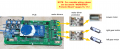
PCB, MC33926, protector and motors
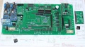
PCB und MC33926
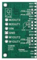
Pin-Belegung
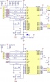
Schaltbild MC33926


Hier findest Du eine Anleitung wie der Motortreiber auf das PCB gesetzt wird.
Für Verkabelung von Motortreiber, Protector PCB und Motoren bitte die Anleitung im Abschnitt "Protector PCB" öffnen.
Protector PCB
![]() Protektorboard: Bei 24V Systemen kommt es zu Spannungsspitzen, die den Motortreiber schnell zerstören können. Daher wurde das Protektorboard entwickelt um dies zu verhindern. Es werden 2 Stück benötigt. Einen für die Antriebsräder und einen für den Mähmotor. Schaden kann das Protektorboard auf keinen Fall.
Protektorboard: Bei 24V Systemen kommt es zu Spannungsspitzen, die den Motortreiber schnell zerstören können. Daher wurde das Protektorboard entwickelt um dies zu verhindern. Es werden 2 Stück benötigt. Einen für die Antriebsräder und einen für den Mähmotor. Schaden kann das Protektorboard auf keinen Fall.
PCB, MC33926, protector and motors
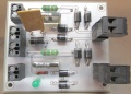
Protector PCB
Protector PCB Verdrahtung
Protector PCB Schaltbild


Anschluss Radmotoren
PCB, MC33926, protector and motors
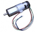
Ardumower Getriebemotor(Welle: 8mm Durchmesser, 5900 U/min, 0.055 Nm, Übersetzung: 1:212, Ausgangs-Drehmoment 2.45Nm, Ausgangsdrehzahl 31 U/min)
Motor wiring
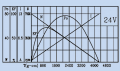
Ardumower Getriebemotor Kennlinie (nur Motor)
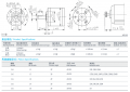
Getriebe-Spezifikation


Die beiden Getriebemotoren werden unabhängig voneinander gesteuert ('Differentialantrieb') :
- Fahren vorwärts/rückwärts
- Lenken links/rechts
Die Eigenschaften der Ardumower - Radmotoren:
- Eine Drehzahl bis zu 31 U/min erlaubt es, den Roboter mit einer ausreichenden Geschwindigkeit von bis zu (Meter/sec = 31rpm/60 * PI * 0.25m = 0.4m/sec) bei Verwendung von Rädern mit 250 mm Durchmesser, zu bewegen.
- ein hohes Drehmoment (2.45 Nm) garantiert, dass der Roboter kleinere Hügel erklimmen kann (mit 2 Motoren, 250 mm Rädern, 31 U/min = 0.4m/s, Beschleunigung = 0.2 ( 1/2 der Nominalgeschwindigkeit) see calculator
- Der eingebaute Encoder kann die Drehzahl messen, die Geschwindigkeit und den Weg feststellen.
- 24V (Laststrom ca. 1A)
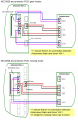
Der linke Getriebe-Motor wird wie folgt an das Protector Board angeschlossen:
Motor Anschluss (linker Motor):
Motor (black)  ==== Protector board Motor_1_OUT(1)
Motor (red)    ==== Protector board Motor_1_OUT(2)
Für den rechten Motor entsprechend an Protector board Motor_2_OUT(1,2) anschliessen.
Anschluss Odometrie der Getriebemotoren
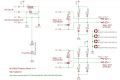
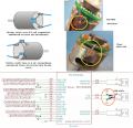
Der im Ardumower-Getriebe-Motor eingebaute Encoder hilft dem Ardumower die Drehzahl bzw. zurückgelegte Distanz zu ermitteln. Hier siehst Du wie die Odometrie der Motoren an das PCB angeschlossen wird.
Motor wiring
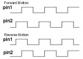
Encoder signal

Motor Odometrie Anschluss (linker Motor):
Motor (brown)  ---- PCB VCC
Motor (green)  ---- PCB GND
Motor (blue)   ---- PCB OdometryLeft (3)
Motor (purple) ---- PCB OdometryLeft (4)
Für den rechten Motor entsprechend an "PCB OdometryRight" anschliessen.
WICHTIG: Bei PCB v0.5/1.2 fehlen die Pull-up Widerstände! Du musst sie nachträglich am PCB wie folgt ergänzen:
PCB OdometryLeft(3) --- 4.7k --- 5v
PCB OdometryLeft(4) --- 4.7k --- 5v
Anschluss Mähmotor
PCB, MC33926, protector and motors
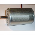
Ardumower Mähmotor
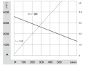
Ardumower Mähmotor -Kennlinie
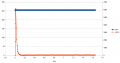
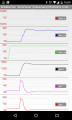
Anlaufstrom
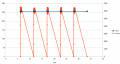
Mähmotor blockiert, 500ms detection (max), waittime: 5sec (min)


Eigenschaften des Ardumower-Mähmotors:
- schnell genug um den Rasen zu schneiden (3150 U/min)
- genügend Drehmoment (140 mNm / 46 W)
- leises Mähen (man hört ihn kaum)
- 24V, Laststrom ~1.0A (L=2.8mH, R=1.9ohm)
Es wird ein MC33926 Motortreiber in Parallelschaltung zur Ansteuerung des Mähmotors verwendet.
![]() Sicherheitshinweis: Entferne zur Sicherheit stets die Messer bei deinen ersten Tests!
Sicherheitshinweis: Entferne zur Sicherheit stets die Messer bei deinen ersten Tests!
Der Mähmotor wird wie folgt an das Protector board angeschlossen:
 Motor (black)  ==== Protector board Motor_1_OUT(1)
 Motor (red)    ==== Protector board Motor_1_OUT(2)
Reduzierung von Motorstörungen
Folgende Anleitung zeigt wie Du Motorstörungen reduzieren kannst.
Reduzierung von Motorstörungen

Motor controller (PID)
Die Geschwindigkeit der Motoren wird mit einem Software-PID-Regler geregelt. Du kannst Dir die Regelung mit der pfodApp anschauen (Plot->Motor control):
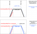
Motor speed settings