Motor-Treiber
Inhaltsverzeichnis
Zusammenfassung
Das Ardumower- Design verwendet zwei verschiedene Typen vo Motoren.Alle Motoren können im Shop shop ![]() ) erworben werden:
) erworben werden:
- Zwei Getriebemotoren als Antriebe (Radmotoren)
- einen Motor (mit hoher Drehzahl) zum Mähen (Mähmotor)
Zur Steuerung der Motoren sind Motortreiber erforderlich.
Spannungen
Obwohl es 12V- und 24V- Motoren gibt,verwendet der Ardumower wie alle modernen Systeme, 24V Motoren. Der Grund ist folgender:
Nehmen wir an, der Motor verbraucht 50W. Bei 24V ist der daraus resultierende Strom: 50W / 24V = 2A. Bei Verwendung von 12V resultiert daraus ein Strom von: 50W / 12V = 4A.
TJe höher der Strom (A), um so mehr Probleme treten auf:
- Der Motortreiber muss für höhere Ströme ausgelegt werden (teurer)
- die Leiterzüge uf der Platine müssen breiter sein (teurer)
- der Akku muss in der Lage sein, höhere Ströme zu liefern (teurer)
Aus diesen Gründen ist der Ardumower als ein 24V-System ausgelegt.
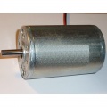
Radmotoren
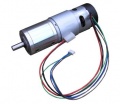
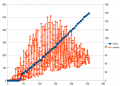
Ardumower Getriebemotor(Welle: 8mm Durchmesser, 5900 U/min, 0.055 Nm, Übersetzung: 1:212, Ausgangs-Drehmoment 2.45Nm, Ausgangsdrehzahl 31 U/min)
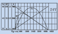
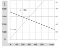
Ardumower Getriebemotor Kennlinie (nur Motor)
Reduzierung der Motorstörungen


Die beiden Getriebemotoren werden unabhängig voneinander gesteuert ('Differentialantrieb') :
- Fahren vorwärts/rückwärts
- Lenken links/rechts
Die Eigenschaften der Ardumower - Radmotoren:
- Eine Drehzahl bis zu 31 U/min erlaubt es, den Roboter mit einer ausreichenden Geschwindigkeit von bis zu (Meter/sec = 31rpm/60 * PI * 0.25m = 0.4m/sec) bei Verwendung von Rädern mit 250 mm Durchmesser, zu bewegen.
- ein hohes Drehmoment (2.45 Nm) garantiert, dass der Roboter kleinere Hügel bis zu 14 Grad erklimmen kann (mit 2 Motoren, 250 mm Rädern, 31 U/min = 0.4m/s, Beschleunigung = 0.2 ( 1/2 der Nominalgeschwindigkeit) see calculator
- Der eingebaute Encoder kann die Drehzahl messen (siehe Odometrie für weitere Informationen) - für die Ardumower-Software sind Encoder erforderlich.
- 24V (Laststrom ca. 1A)
Motor driver
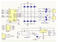
A motor driver is a circuit that allows current to flow either one direction or the opposite direction through the motor - depending on wether the motor should turn forward or backward (so called 'H-bridge'). There are many motor drivers available as ready-circuit boards, some can even control two motors (Dual H-Bridge) - if you connect two of their H-bridges in parallel, the maximum motor current can be increased.
If the direction of the motor does not need to be controlled, (e.g. for the blades), you do not need an H-bridge, but instead a simple 'switch' (e.g. MOSFET-transistor-circuit).
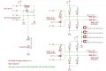
The motor driver is connected through control signals to the Arduino. Example:
 Arduino Digital Pin  —>  MOTOR-Direction Pin (DIR)
 Arduino PWM Pin      —>  MOTOR-Speed Pin (PWM)
 Arduino Analog Pin   <—  MOTOR-Current Sensor Pin
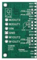
One pin controls the direction (forward/backward), the other pin controls the speed. One analog input pin is connected to the current sensor. The current sensor module (ACS712-05A) is connected in series with the motor.
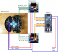
NOTE: only for demonstration! See real schematics for concrete wiring

PWM frequency
The speed of the motor is controlled by a PWM duty signal. We use the Arduino default PWM frequency (490 Hz) to control the motor drivers.

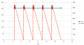
Arduino PWM duty signal
PWM 490 Hz: odometry ticks, sense (current)
PWM 3.9 Khz: odometry ticks, sense (current)

PWM 20 Khz: odometry ticks, sense (current)
PWM 31 Khz: odometry ticks, sense (current)


Popular modules
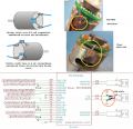
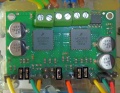
MC33926 (recommended)
Features: up to 3A with integrated current sensor and thermal shut-down protection, for all kind of robot mowers)
pinout
jumpers
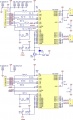
schematics
automatic current limiter
Motor start 50% PWM transients
Peak/EMF protection


M1_FB     --- pinMotorLeftSense A1
M1_SF     --- pinMotorLeftFault 25
M1_PWM_D1 --- connect with jumper to GND
M1_PWM_D2 --- connect with jumper to VDD
M1_IN1    --- pinMotorLeftPWM 5
M1_IN2    --- pinMotorLeftDir 31
EN        --- pinMotorEnable  37
M2_FB     --- pinMotorRightSense A0
M2_SF     --- pinMotorRightFault 27
M2_PWM_D1 --- connect with jumper to GND
M2_PWM_D2 --- connect with jumper to VDD
M2_IN1    --- pinMotorRightPWM  3
M2_IN2    --- pinMotorRightDir 33
EN        --- pinMotorEnable  37
VDD       --- Arduino 5V
L6201P
L6201P PCB

L6201P datasheet


Features: 48V, 4A
B+     power supply output voltage equal to the power connector
GND    GND
EN     driver enable
RPWM   forward PWM signal, active HIGH
LPWM   reverse PWM signal, active HIGH
CT     current signal output
VT     voltage signal output
Forward   EN=1, RPWM=PWM, LPWM=0
Reverse   EN=1, RPWM=0,   LPWM=PWM  (also possible?   EN=1, RPWM=255-PWM, LPWM=1  => needs to be verified!)
Brake     EN=1, RPWM=0,   LPWM=0
Not brake EN=0, RPWM=x,   LPWM=x
Note: 1=High level (3.3-5v), 0=Low level (0V or GND)
L9958
Features: Arduino 240W H-bridge Motor Driver Board - SX8847, up to 8A
Note that this module has an on-board linear voltage regulator, which converts the input POWER (typically 24 or 12V) to 5V. Some modules do this with a single voltage regulator (chip VR1 on the module), or in a two-staged approach (VR1 and U2).
Converting 24V to 5V with a linear voltage regulator is very inefficient (current in = current out, so if you need 100mA at 5V, the linear voltage regulator requires 100mA at 24V, so you loose 1.9W in this module). Therefore, it is recommended to disconnect the linear voltage regulator from the board, and use the 5V from the switched mode power supply.
L9958 GND---GND
L9958 VCC---Arduino 5V
L9958 EN---Arduino 5V
L9958 DI---GND
L9958 DIR---Arduino MOTOR_DIR
L9958 PWM---Arduino MOTOR_PWM
L9958 MOTOR(+)---motor(+)
L9958 MOTOR(-)---motor(-)
L9958 POWER(+)---battery(+)
L9958 POWER(-)---battery(-)

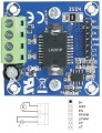
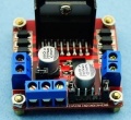
L298N
Features: up to 4A Notice: When using a L298N-motor driver, both H-bridges (2A) should be connected in parallel, so that both bridges drive a single motor (max. 4A):
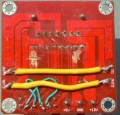
Connect in parallel:
IN1 with IN4
IN2 with IN3
OUT1 with OUT4
OUT2 with OUT3
(Do NOT disconnect the SENSE-lines, except when you want to measure current by a 'shunt' resistor).
Make sure there is a jumper on both ENA and ENB. Also, make sure there is a jumper on S1.
driver
double current
schematics


Mower motor and driver
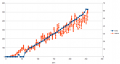
Ardumower mower motor
Ardumower mower motor curve
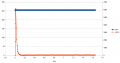
Mower start current
Mower blocked, 500ms detection (max), waittime: 5sec (min)


The Ardumower mower motor features:
- Fast enough to cut the lawn (3150 rpm)
- Enough torque (140 mNm / 46 W)
- Quiet mowing (you cannot hear it)
- 24V, load current ~1.0A (L=2.8mH, R=1.9ohm)
For a the mowing motor, a MOSFET circuit is used. The MOSFET transistor IRLIZ44N (alternatives: IRF1404, IRL540N, RFP30N06LE, FQP30N06L) can already switch a current of 30A at the Arduino 5V control signal (N-LogL). The 10K resistor pulls down to ground when the Arduino starts. The 180 Ohm resistor limits the current at the Gate caused by level switches to about 30mA. The diode (MBR1045) protects the circuit against current caused by motor induction. A current sensor module (ACS712-30A) is connected in series with the motor.
![]() Security note: For security reasons, always remove mower blades in your first tests!
Security note: For security reasons, always remove mower blades in your first tests!
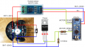
NOTE: only for demonstration! See real schematics for concrete wiring

Choosing a driver
When purchasing a motor driver, consider...
- max. thermal load (short-circuit current)
- price
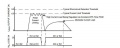
Starting current
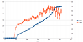
Here are some measurements of the Ardumower motor's starting current (peak):
Starting current:
- Gear motor: 15A (starting current peak)
- Mowing motor: 20A (starting current peak)
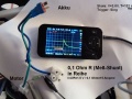
Gear motor start current (peak)

Short-circuit current
To not damage the motor driver on the first run, find out the maximum current that can flow through your motors. In other words, find out the 'short-circuit' current. Typical measurement installation:
Battery === Ampere meter === Motor
The Amperemeter (e.g. model making) should be able to measure the maximum current (e.g. 30A). The motor to be measured is mechanically blocked (so it cannot rotate).
Warning
- always remove blades
- only connect battery for a short period (1-5 seconds)
- always use cables with sufficient wire cross section
Example measurement:
- Rotenbach SPM08-320
- Wheel motor: 8A
- Mowing motor:
- Ambrogio L50
- Wheel motor: 4,5A
- Mowing motor: 22A
- Tianchen TC-G158
- Wheel motor: 5,4A
- Mowing motor: 16A (both 32A)
The measured current will only flow in 'worst-case' scenarios, which means when the motor starts or when it is blocked and it will only flow for a short time (as your battery might not deliver the high current constantly, and so current and voltage will break down).
Current sensor
To detect certain conditions (robot drives against obstacle, motor blocks etc.), the motor current should be monitored constantly. There are two approaches for sensing current.
Approach "Hall sensor module"
This is the recommended approach for sensing current. These current sensor modules are available for different current ranges.
- ACS712ELC-05A (185mV/A, max. 5A)
- ACS712ELC-20A (100mV/A, max. 20A)
- ACS712ELC-30A (66mV/A, max. 30A)
- The lower the range, the more precise the measurement.
Approach "Shunt resistor (circuit)"
The current flows across a very small resistor (0.5 Ohm) and the voltage drop is measured
