Raindancer Firmware (English): Unterschied zwischen den Versionen
Roland (Diskussion | Beiträge) K (→RTC) |
Roland (Diskussion | Beiträge) K (→EEPROM) |
||
| Zeile 771: | Zeile 771: | ||
==EEPROM== | ==EEPROM== | ||
| − | + | The EEPROM is used on the RTC. Currently it is used to store statistics. The following statistics are stored: total mowing time, total distance traveled, total number of rotations, number of loading operations. | |
| − | + | The use of the EEPROM is switched on with the following line in the config.h: | |
#define CONF_DISABLE_EEPROM_SERVICE false | #define CONF_DISABLE_EEPROM_SERVICE false | ||
| − | + | The following commands are available for the EEPROM: | |
eep.config //show EEPROM service config | eep.config //show EEPROM service config | ||
| Zeile 788: | Zeile 788: | ||
eep.erase //erase the eeprom | eep.erase //erase the eeprom | ||
| − | + | To test the EEPROM e.g. enter the following command: | |
eep.set.f,10,7.3 | eep.set.f,10,7.3 | ||
| − | + | This writes the float value 7.3 to the addresses 10, 11, 12, 13 in the EEPROM. | |
| − | + | With the command | |
eep.f,10 | eep.f,10 | ||
| − | + | the value can then be read out again. | |
| − | + | The command eep.erase deletes the first 3 pages of the EEPROM. The other pages are currently not deleted because they are not used. | |
eep.erase | eep.erase | ||
| − | + | It makes sense to erase the EEPROM after the enable the service so that the memory cells are initialized. | |
==Geschwindigkeit am Perimeter verlangsamen== | ==Geschwindigkeit am Perimeter verlangsamen== | ||
Version vom 31. Mai 2018, 10:18 Uhr
!!! I am currently translating this side. !!!
Attention! The software is still changing and can be changed / extended at any time.
Inhaltsverzeichnis
- 1 Download
- 2 Overview
- 3 For minimum commissioning, the following requirements should be met
- 4 Optional can be used
- 5 config.h
- 6 QUICK START TO MOW
- 6.1 Errorhandling
- 6.2 To get warm: Configuration of the battery service
- 6.3 Commissioning of the motors
- 6.4 Commissioning the encoder
- 6.5 Check of the closed loop control service
- 6.6 Check the position control services
- 6.7 Mowmotor commissioning
- 6.8 Perimeter Commissioning
- 6.9 Configure Bluetooth
- 6.10 Configure Arduino Central
- 6.11 First test drive
- 7 TUNE UP
- 7.1 Configure the bumpers on the bumper connectors
- 7.2 Charge Service
- 7.3 Watchdog
- 7.4 Undervoltage Shutdown
- 7.5 I2C Bus
- 7.6 RTC
- 7.7 EEPROM
- 7.8 Geschwindigkeit am Perimeter verlangsamen
- 7.9 Mähmotorstrom einstellen
- 7.10 Langsamer fahren, wenn Mähmotor belastet
- 7.11 Spiralfahrt
- 7.12 Perimeter Tracking
- 7.13 Schnelle Rückkehr
- 7.14 Mähzonen zwischen aneinander liegenden Flächen
- 7.15 Verlegung des Perimeterkabels an Ecken
- 8 Perimeter Sender
- 9 Troubleshooting
- 10 Understanding the Behaviour Tree
Download
(Auf Github mit dem grünen Button das Zip-File herunterladen)
The Raindancer firmware is located in the directory code\Raindancer
The transmitter firmware is located in the directory code\sender
Overview
The Raindancer firmware is based on the code of the Nucleomower which was realized with the development board STM32 Nuleo 411RE in 2016/2017. The firmware was then converted to Ardumower PCB 1.3 in 2017/2018. It pursues the goal of getting a stable system with as little hardware as possible, which works all year round and provides a good mowing result with the chaos principle.
The firmware has following 'Workflow' : The Mower is in the charging station. The Mower drives from the charging station a predetermined distance along the perimeter to an area and then begins to mow after the chaos principle. The mowing time is approx. 130min-150min with the original Ardumowerkomponents. After the battery voltage has dropped to 23.7V, the robot looks for the perimeter cable and drives it to the charging station. Once in the charging station, the battery is charged. The next mowing operation is restarted via the mobile phone with a range command. (The robot can also be operated without a charging station.)
The firmware was developed for robots with the drive motor rear, but can also be used for the original Ardumower chassis. Optimizations for the original Ardumower chassis will be made later. The Mower turns on the perimeter. If a coil has passed over the perimeter cable, the robot will continue driving for approx. 20cm. Then both coils are turned into the loop and from then on it will be further rotated at a random angle. Since the original Ardumower chassis has a short distance between spools and wheels, here is the workaround: In the config.h can be set that the Mower drive back a certain way, then turns a fixed angle (rotation simulated on the perimeter) and after the turning the fixed angle, the random angle is rotated.
Internally in the firmware, distances are traveled in cm. This means that encoders are needed.
For the 'Perimetererkennung' a 128-bit signal is used. Therefore, the Raindancer transmitter (sender) software must be installed on the transmitter. 2 perimeter receivers are needed. As you approach the perimeter cable, the robot slows down. If the robot does not recognize the signal for 2 seconds, it stops and switches off the motors. If it recognizes the signal again, it continues.
In the current version, the firmware supports a pass through charging station (supporting a single-sided charging station follows at a later date). Using the charging station can be switched off in the software. Then the robot stops at the perimeter when the battery voltage drops below 23.7V. For charging, the robot can then be switched off, connected to the charging cable and switched on again. The robot then goes into charging mode. If the voltage drops below 21.7V, the undervoltage trip will trip if it is not bypassed.
With the original motors and wheels, the robot drives at a speed of approx. 1200m / h. In order to get a reasonable cut, the robot has to mow about 6-9 hours a day for a 1000m² area (my experience). Of course, it also depends on the type and shape of the lawn area. For acceleration and deceleration, the Simple Trajection Planner is used by the Linux CNC project. This allows a very smooth start and braking.
If an original Bumperduino, Bumper with switches, Hall Effect sensors, ... are used, they can be connected to the Bumper Pins as before.
The firmware was optimized for 'not with the perimeter wire fenced obstacles' on the lawn. Instead of driving at full speed against the obstacle, the speed is reduced from a certain distance and drove gently against the obstacle. Prerequisite for this are sonar sensors. This feature is optional. The robot supports a self-made Bumperduino with two MaxSonar sonar sensors and an MPX5010DP FREESCALE pressure sensor for a pressure wave hose.
https://github.com/kwrtz/Raindancer/blob/master/DipTrace/DistanceBumperSensor/DistanceBumperSensor.pdf
The evaluation is done by an Arduino Nano, which is connected to the PinUserSwitch2 / 3 of the PCB1.3. Upon detection of an obstacle with the sonar sensors, the robot slows down and bumped gently against the obstacle where the bumper or bumper duo triggers. The board is relatively simple. This allows them to be easily soldered together on a laboratory board. The MaxSonar sensors can be omitted and a separate solution can be connected to the Nano. The sensor for the pressure wave hose can be omitted and only the sonar sensor is used. Another option for an approach solution is to expand the current Raindancer software. The original Ardumower ultrasonic sensors are currently not supported.
The serial interface is used for the operation. On the mobile phone is the software Arduino Central is used (free with advertising or without advertising for a few euros). In Arduino Central, buttons can be configured with commands. The operation is via command line commands. The send line must be terminated with CR. The output is automatic shown on the console or on the mobile phone, depending on where the command was just entered. Most commands are grouped by services. The group corresponds to the services mentioned in the software. The command following the service is then separated by a dot. Spaces are skipped and have no meaning. This is useful when using the mobile phone, where a space is inserted after a period.
Example: clc.enc
The service clc contains the command enc. This addresses the closes loop control service and tells it to show the encoder data.
Parameters are separated by a comma.
Example: pc.cm,60,30 //drives 60 cm with speed 30 (//drives... does not belong to the command)
This addresses the Positioncontrol service. Drive 60cm at the speed of 30%
The command H displays the help..
Many commands shows an output on the console. To disable this output, you can enter h or the same command (which triggered the output). If an error or motor stall is shown, it can be reset with the reset command.
The software is modular. The individual modules are hardly influence each otherl. This makes it relatively easy to modify or extend something.
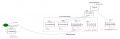
https://github.com/kwrtz/Raindancer/blob/master/Documentation/SoftwareStructure.pdf
The UMLET software was used to display and edit the Structure software.
There is a hardware abstraction layer. All communication with the hardware is done through objects in hardware.h. Most objects in hardware.h are defined in InOutInterface.h. In hardware.cpp the initialization and pin assignment of the hardware takes place. Services collect data or control the motors and make their service available to the controllogic. A behavior tree is used for the controllogic. The behavior tree accesses the services via the blackboard. Nodes of the Behavior Tree exchange information about the Blackboard.
SPLAN was used for the graphic creation of the BHT.
https://www.electronic-software-shop.com/elektronik-software/splan-70.html?language=de
To view the files of the BHT the following free software can be used:
https://www.electronic-software-shop.com/support/kostenlose-datei-viewer/?xoid=oep38ca4ehqn37a7dn3rnrpie6
The files of the BHT are here:
https://github.com/kwrtz/Raindancer/tree/master/Documentation
The robot knows two modes: Manual and Auto. In manual mode, all services are running, but the Behavior Tree (BHT) is off. In auto mode, the BHT is activated.
Which modes will start when:
MANUAL  Robot is switched on and is not in the charging station
AUTO    The robot is switched on in the charging station and detects a voltage at the charging contacts. Behavior charging is activated. The robot is loading
If the robot is in MANUAL mode, it can be switched to automode using command A. If the robot then recognizes the perimeter signal, it starts mowing.
Open points
- Stability of the software in the long term. Stand 28.04.2018 Currently, the current software version mowed 63h, has traveled 59km and has rotated 8426 times
- The line tracking algorithm has been recently optimized for the rear wheel drive chassis. Due to the short distance between coil and the wheels of the original Ardumower chassis, it may be necessary to program another algorithm.
- Optimization for the original Ardumower chassis (Mowing works very well with the workaround, if necessary, play with the parameters CONF_PER_CORRECTION_ANGLE and CONF_PERIMETER_DRIVE_BACK_CM)
- Dodge objects close to the perimeter (SecondReverse2 in the BHT)
- Program one-sided accessible charging station
- Use RTC to program start at a defined time
Other wishes
- Integrate rain sensor
- The charging station is currently only counterclockwise approached.
- Amplify the signal of the charging station to + -20V voltage stroke
- SRF08 integration
- Integrate I2C temperature sensors
- An external start / stop button that starts or stops mowing
- Approachthe charging station with GPS. Drive 15m before the charging station on the perimeter and then drive into the charging station..
- GPS map - the mower may not recognize the signal in the middle of the lawn because the signal is too weak. You can then use GPS to see if you are on the lawn area. If you now say that the signal must be detected at least 15m away from the perimeter, you can neglect the signal within the area if the GPS signal indicates that you are on the lawn.
- GPS Map - Note where mower has already mowed. Then mow in less mowed areas if necessary.
The GPS card will probably have to be outsourced to an external processor
For minimum commissioning, the following requirements should be met
![]() Safety note: For safety reasons, the mower blades must not be mounted during the first tests!
Safety note: For safety reasons, the mower blades must not be mounted during the first tests!
![]() Important: For the first gearmotor tests, the robot should be jacked up so that the wheels are not in contact with the ground!
Important: For the first gearmotor tests, the robot should be jacked up so that the wheels are not in contact with the ground!
- PCB1.3 with Arduino DUE
- Original Ardumower drive motors with encoder
- Original Ardumower mowing motor
- Two Ardumower perimeter coils front left / right. Mounted on original Ardumower chassis if necessary: Left / center (depends on which line tracking algorithm one uses)
- BT module
- The bridge for the encoders on the PCB1.3 is bridged to the 2-divider.
- 24V power supply
Optional can be used
- RTC with EEPROM
- Ardumower Bumper Pins with switches, Hall effect sensors, original Bumper Duino, ...
- Pass through charging station
- Self-built Bumperduino with 2MaxSonar sensors on PinUserSwitch2 / 3
config.h
The file config.h contains the basic configuration of the firmware.
'Before commissioning the parameters must be adjusted.'
Select the chassis form. Only one parameter may be set to true.
#define ARDUMOWER_CHASSIS  false
#define PARANELLO_CHASSIS  false
#define RAINDANCER_CHASSIS true
In config.h go then to the code section, which belongs to your choice and change this section. For the Ardumower chassis the section starts with following:
//======================================================================================================================
// CONFIG FOR ARDUMOWER CHASSIS
//======================================================================================================================
Console Speed:
#define CONF_PC_SERIAL_SPEED 115200 // Speed serial consol
If the Bluetooh module has already been configured with the Azurit firmware, the line
#define CONF_BT_SERIAL_SPEED 115200
has to be changed to:
#define CONF_BT_SERIAL_SPEED 19200
Setting the wheel circumference and wheel distance. The original Ardumower wheel has a circumference of 78.54f cm
#define CONF_RADUMFANG_CM			80.738f // Wheel circumfence in cm original ardumower: 78.54f
#define CONF_DISTANCE_BETWEEN_WHEELS_CM		36.0f	// Distance where the wheels hits the ground do not measure on top of the wheels!!!
For the first startup most services should be disabled to prevent error messages:
#define CONF_ENABLEWATCHDOG             	false   // Set to false to disable Watchdog. true to enable.
#define CONF_DISABLE_RANGE_SERVICE		true    // Disables my own range sensor running on bumper duino on pinUserSwitch3 => diNearObsacleSensor
#define CONF_DISABLE_BUMPER_SERVICE		true   // Disables original bumper sensor pins (PCB1.3) on pinBumperLeft => diBumperL and  pinBumperRight => diBumperR
#define CONF_DISABLE_BUMPERDUINO_SERVICE	true   // Disables my own bumper duino sensor on pinUserSwitch2 => diBumperSensor
#define CONF_DISABLE_PERIMETER_SERVICE	        false   // Disables perimeter sensor
#define CONF_DISABLE_RTC_SERVICE		true    // Disables rtc sensor
#define CONF_DISABLE_EEPROM_SERVICE		true   // Disables EEPROM requests
#define CONF_DISABLE_BATTERY_SERVICE	        true   // Disables battery sensor
#define CONF_DISABLE_CHARGE_SERVICE		true   // Disables charge system service
#define CONF_DISABLE_MOTOR_STALL_CHECK  	true   // Disables the motor stall/encoder check in closed loop control
#define CONF_DISABLE_MOW_MOTOR          	false   // Disables the mow motor
#define CONF_DISABLE_CHARGINGSTATION true
'ONLY for the original Ardumower chassis design' the following constants should be set to optimize the rotation at the perimeter
#define CONF_PER_CORRECTION_ANGLE       30
#define CONF_PERIMETER_DRIVE_BACK_CM    40.0f
Since compiling is done more often, it makes sense to jack up the robot so that the drive wheels and the mower motor can rotate freely.
After the first compile, upload and start of the firmware, the last line should be:
Press H for help.
Enter H here. Thereafter, all available commands are displayed. It is a good ideas to copy and save the commands to a file, so that you can look at it when you need.
If after compilation following warning occure, they can be ignored:
pinman.cpp: 18:0: warning: "PWM_FREQUENCY" redefined [enabled by default]
  #define PWM_FREQUENCY 3900
pinman.cpp: 19:0: warning: "TC_FREQUENCY" redefined [enabled by default]
  #define TC_FREQUENCY 3900
QUICK START TO MOW
The aim of this chapter is to become more familiar with the operation, and to configure the robot to the extent that the perimeter sensors work and you can mow within the perimeter.
The robot is connected via the console cable. Speed: 115200
Errorhandling
If the firmware detects an error, this goes into the Errormode. The Mower stops and the mow motor is switched off. The services continue to run. The first error occurred is latched. The error is then sent to the console or bluetooth (BT) every 2 seconds, depending on what was last active or activated by sending a character. If you has started the mower via Bluetooth, the error is then shown on BT.
To disable the error, the following commands must be entered one after the other:
reset     //reset error and motor faults
M         //activate manual mode
The error command can be used to display the error log. The error log shows the history of the traversed running nodes of the BHT as well as various other events. It is 5000 characters tall.
error //show errormessage
The show.hist command displays the last direction of rotation and other parameters.
show.hist //show history
The last entered values will be displayed first, so that they are above!
After disabling the error, the Mower can be started again with:
A
However, both coils must be in the perimeter for that.
To get warm: Configuration of the battery service
The battery service determines the voltage of the battery and makes it available to the BHT.
Activate the battery service in config.h and then re-install the software.
#define CONF_DISABLE_BATTERY_SERVICE false
Enter the command: bat.show It should display the correct battery voltage.
If this deviates by more than 0.2V, then this can be adjusted with the constants #define BATTERYFACTOR_BS 11.0f // Equivalent to (100 + 10) / 10 Voltagedivider #define DIODEDROPVOLTAGE_BS 0.4f These constants are defined in batterySensor.h.
The voltage in batterySensor.h is calculated as follows
sensorValue = aiBATVOLT.getVoltage();
float readVolt = sensorValue * BATTERYFACTOR_BS + DIODEDROPVOLTAGE_BS; // The diode sucks 0.4V
Commissioning of the motors
The first thing to check is whether the motors are turning and whether they are turning in the right direction. For this purpose, the motors are controlled directly with a PWM specification. This means, there is no control of the speed based on the encoder. The speed control loop is open (open loop);
The command clc.mt, 1,150 causes the clc service to send the input PWM of 150 directly to the motor. Maximum for the PWM is 255. A 1 controls the left engine, a 2 the right.
Enter the command:
clc.mt,1,150
This activates the motor (1) on the left directly with a PWM of 150. The wheel is then Stopped with:
clc.mt,0,0
The wheel on the left should turn forward. If it turns backwards, the cable at the plug must be reversed. Should the wheel not turn, it can still be tried with a higher PWM of e.g. 200. The wheel should definitely turn even at a PWM of 50 (better less).
The same for the right wheel (2):
clc.mt,2,150
The wheel is then Stopped with:
clc.mt,0,0
Anmerkung:
Die PWM für die Motoren läuft mit 3900Hz.
Wenn man die Originalwerte verwenden möchte, muss man nachfolgende Zeilen in pinman.cpp abändern.
#define PWM_FREQUENCY 3900
#define TC_FREQUENCY 3900
Achtung: Wenn die PWM zu hoch gesetzt wird, z.B. 18000Hz, dann drehen sich die Räder bei niedriger PWM von z.B. 60 nicht mehr. Es kommt dann ein Fehler, dass bei Vorgegebener PWM von 60 die Geschwindigkeit 0 ist.
Commissioning the encoder
It it checked if the encoders work and if they count in the right direction.
The encoder routine has two counters per wheel. Once an absolute counter (absEnc), which always counts positive no matter in which direction the wheel turns. And a positive / negative counter (enc), which counts up when driving forward and counts down when reversing.
Enter the command
clc.mt, 1,150
to make the left wheel turn.
Enter then
clc.enc
This will display the encoder values from the left and right wheels.
The output is terminated with the command: h.
Both displayed counters of the left wheel (1) must now count up.
Example:
Engine 1 = left - should not count if only the right engine is running.
Engine 2 = right - should not count if only the left engine is running.
! 03, motor 1 enc: 972 absEnc: 972 rpm: 2.596326 m / h: 125.773315 deltaTicks: 2 deltaTime: 32986us
! 03, motor 2 enc: 974 absEnc: 974 rpm: 3.325853 m / h: 161.113647 deltaTicks: 2 deltaTime: 33445us
! 03, motor 1 enc: 974 absEnc: 974 rpm: 2.923552 m / h: 141.625061 deltaTicks: 2 deltaTime: 33156us
! 03, motor 2 enc: 975 absEnc: 975 rpm: 2.678638 m / h: 129.760696 deltaTicks: 1 deltaTime: 33144us
! 03, motor 1 enc: 976 absEnc: 976 rpm: 3.132316 m / h: 151.738159 deltaTicks: 2 deltaTime: 32857us
! 03, motor 2 enc: 976 absEnc: 976 rpm: 2.296233 m / h: 111.235962 deltaTicks: 1 deltaTime: 32859us
! 03, motor 1 enc: 978 absEnc: 978 rpm: 3.251686 m / h: 157.520752 deltaTicks: 2 deltaTime: 32998us
The example shows that the encoders are counting up. 'Example motor 1' : enc: 972 then enc: 974, then enc: 976 ... 'Example motor 2' : enc: 972 then enc: 975, then enc: 976 ...
If the enc value counts negative when driving forward you can configure it in the config.h:
#define CONF_LEFT_ENCODER_INVERSE false
#define CONF_RIGHT_ENCODER_INVERSE false
To do this, set CONF_LEFT_ENCODER_INVERSE to true for the left wheel. Set CONF_RIGHT_ENCODER_INVERSE to true for the right wheel.
Do the same for the right wheel:
clc.mt, 2,150
Command is stopped with clc.mt, 0,0.
After the lines in the config.h have been set correctly, recompile, play and retest!
Check of the closed loop control service
The closed loop control (clc) service controls the speed of a wheel and thus also the straightforward movement of the robot. There is one service for each wheel so there are two services in total. The service internally calculates the speed of the wheel with the aid of the encoder values and then sets the necessary PWM to reach the specified speed (closed loop). The speed is given in%. 100% refering to the constant CONF_MAX_WHEEL_RPM in the config.h.
With the command clc.v,30 both services are commanded to turn the wheel at a speed (v) of 30%. Thus, both wheels should turn forward.
Enter:
clc.v, 30 Moving forward with speed 30%
then
clc.v, s stop engine
then
clc.v, -30 drives reverse with speed 30%
If everything is working, then continue. Otherwise check encoders and drivedirection again.
mot.cur Shows the motor current.
Check the position control services
The Position Control Service (pc) is used to drive the wheel a certain way or to turn the wheel a certain angle. There is one service per wheel. With the command pc.a,360,80 both wheels are comanded to: Turn the wheels an angle of 360 degrees with a maximum speed of 80%.
Make a mark on a wheel to see how far it turns.
pc.a, 360,80  Rotates both wheels forward by 360 degrees with 80% speed if everything is configured correctly.
pc.a, -360,80 Rotates both wheels backwards by 360 degrees with 80% speed if everything is configured correctly.
The Position Control can be stoped with the command
pc.s
If the wheel does not turn 360 degrees, the value CONF_ENCTICKSPERREVOLUTION in config.h appears to be wrong. For the original engines from the Ardumower shop, the value of 1060 is given.
In addition, the constant CONF_RADUMFANG_CM is important for the calculation to be correct to drive a particular path in cm.
Since the engine monitoring was switched off in the beginning in the config.h, it is now time to switch on again. Motor monitoring checks whether the encoders deliver values when the motors are turning, whether they are turning in the right direction, or whether the motor is actually turning when a PWM is applied.
To enable motor monitoring in config.h, set the value CONF_DISABLE_MOTOR_STALL_CHECK to false.
#define CONF_DISABLE_MOTOR_STALL_CHECK false
Recompile and upload. Then try again. No errors should be displayed.
If everything works, the robot can be put on the wheels.
Further tests can still be performed (note that the USB cable should be long enough, preferably use an extension);
Drive a certain way in cm
pc.cm, 60,30 drives 60cm forward with the speed of 30%
pc.cm, -60,30 drives 60cm backwards with the speed of 30%
Turning a certain angle. Prerequisite: CONF_ENCTICKSPERREVOLUTION, CONF_RADUMFANG_CM and CONF_DISTANCE_BETWEEN_WHEELS_CM are configured correctly.
turnto, 360,30 Turn the robot 360 degrees CW (clockwise)
turnto, -360.30 Turn the robot 360 degrees CC (counter clockwise)
If the robot does not turn 360 degrees, the constant CONF_DISTANCE_BETWEEN_WHEELS_CM in config.h is probably wrong.
Mowmotor commissioning
The mowing motor does not use an encoder. It is operated with a PWM of 255. The PWM of 255 is not immediately given to the engine. It ramps up the PWM from 0 to 255. The same applies to the braking of the engine. It may happen that a motor fault is displayed when the engine is decelerating. This is because the inertia of the mowmotor disc tends to continue to rotate the motor, thus retroactively injecting a current into the motor driver that exceeds the limits such that the tri-state outputs of the driver go to high-impedance. If this happens, the error can be reset with the reset command.
Befehl eingeben:
z //mow motor start
danach
t //mow motor stop
It may be that when stopping the motor a fault comes up. Reset this with the command reset.
mot.curm //indicates the mowing motor current.
If the PCB1.3 is used, the mower motor current is probably displayed incorrectly here. See: Adjusting the mower motor current in Tune Up
This can be done later and is not so important for the first mowing operation.
Perimeter Commissioning
The Raindancer firmware works with two coils. This determines the angle at which the robot meets the perimeter. Accordingly, it is decided whether CC or CW is rotated. The perimeter signal must be received all the time while mowing. If the signal is not received for 2 seconds, the robot will stop and continue as soon as the signal is received again. The time that a non-receive is tolerated is set with the parameter CONF_PER_SIGNAL_LOST_TIME in the config.h. With this it is possib to bridge "Receiving holes" in the middle of the lawn. Disadvantage is, if the transmitter fails exactly when the robot is at the perimeter, it may be that the robot travels this set time outside the perimeter loop.
Prerequisite for commissioning: The spools of the robot must be within the perimeter loop for commissioning. The Raindancer transmitter firmware must be installed on the transmitter.
First check is if the signal is detected.
You can see the calculated value of the individual coils as follows:
per.resultl for left coil
and
per.resultr for right coil.
The example below shows that the BAD has not received a valid signal. It is important here that no BAD is displayed. The received amplitude is behind mag :. The signal quality can be seen on the Peak Signal Noise Ratio psnr.
Beispiel per.resultl
mag:  453  peak @ 432 :  453   peak2 @ 328 :  142   MSE: 1704.569   psnr:  120.388   psnr2:   11.829   ratio:   10.177
mag:  431  peak @ 279 :  431   peak2 @ 145 : -125   MSE: 1638.841   psnr:  113.349   psnr2:    9.534   ratio:   11.889
mag:  372  peak @ 128 :  372   peak2 @  12 :  119   MSE: 1521.076   psnr:   90.978   psnr2:    9.310   ratio:    9.772
mag:  458  peak @ 486 :  458   peak2 @ 352 : -195   MSE: 1922.495   psnr:  109.110   psnr2:   19.779   ratio:    5.516
mag:  428  peak @ 335 :  428   peak2 @ 233 :  118   MSE: 1818.376   psnr:  100.740   psnr2:    7.657   ratio:   13.156
Beispiel per.resultr
mag:    6  peak @ 144 :    6   peak2 @  24 :   -5   MSE:    3.161   psnr:   11.388   psnr2:    7.908   ratio:    1.440    BAD
mag:   -5  peak @ 161 :   -5   peak2 @  46 :    4   MSE:    2.380   psnr:   10.504   psnr2:    6.723   ratio:    1.562    BAD
mag:   -5  peak @  60 :   -5   peak2 @ 179 :    5   MSE:    3.556   psnr:    7.030   psnr2:    7.030   ratio:    1.000    BAD
mag:    5  peak @ 159 :    5   peak2 @   3 :    4   MSE:    2.949   psnr:    8.477   psnr2:    5.425   ratio:    1.563    BAD
mag:    5  peak @  11 :    5   peak2 @ 153 :    5   MSE:    3.286   psnr:    7.607   psnr2:    7.607   ratio:    1.000    BAD
End the output with h.
Both coils should detect the signal, so do not indicate a BAD. Also not sporadicly!
Next, the polarity of the signal must be configured. Enter:
per.show. (switch off output with h)
If the coil is inside the perimeter, the amplitude of the coil must be positive.
The detected perimeter amplitudes are now shown. ML indicates the amplitude of the left coil, MR the amplitude of the right coil.
!03, ML: -305  MR: 331 magMax:332 magMedL%: 0 magMedR%: 102
!03, ML: -330  MR: 338 magMax:332 magMedL%: 0 magMedR%: 102
!03, ML: -327  MR: 330 magMax:332 magMedL%: 0 magMedR%: 102
!03, ML: -336  MR: 332 magMax:332 magMedL%: 0 magMedR%: 102
!03, ML: -304  MR: 328 magMax:332 magMedL%: 0 magMedR%: 102
!03, ML: -326  MR: 324 magMax:332 magMedL%: 0 magMedR%: 102
However, one can see here that the magnetude on the left coil is negative. Inside the perimeter loop, this must be positive.
This can be set in the config.h:
#define CONF_LEFT_COIL_INVERSE		true
#define CONF_RIGHT_COIL_INVERSE        false
After new compiling, the values should be positive.
Attention, with per.resultl and per.resultr, the sign of the amplitude is displayed as actually received, regardless of the settings in CONF_LEFT_COIL_INVERSE and CONF_RIGHT_COIL_INVERSE.
It may be that per.resultl provides a positive amplitude and per.resultr a negative amplitude inside the perimeter. That's OK, since it depends on the connection of the coils. Conversion with CONF_LEFT_COIL_INVERSE / CONF_RIGHT_COIL_INVERSE takes place later in the software.
It is important to configure CONF_LEFT_COIL_INVERSE and CONF_RIGHT_COIL_INVERSE so that per.show displays positive amplitudes within the perimeter.
Configure Bluetooth
If the module has already been configured with the original Ardumower software, can CONF_BT_SERIAL_SPEED=19200 be set.
#define CONF_BT_SERIAL_SPEED 19200
(The perimeter outputs are extremely large.) It may be that the software faltered at this transfer rate when viewing perimeter data over BT at that baud rate.) This would be the configuration then done.
Since there are sometimes problems with the configuration of BT modules, I suggest to reprogram a working BT module only if you have another working BT module in reserve.
For the configuration of the BT the original Ardumower routine is used. However, the baud rate is set to 115200.
Therefore, you can use the tips used for troubleshooting in the forum.
Lets start:
De-energize the PCB (also disconnect USB from the DUE). Press and hold button on BT module. Turn on the board.
The BT module should now flash every 2 seconds.
Release the button. Reconnect the USB to the DUE. The BT module should still be flashing every 2 seconds.
Now try bt.show first, to see if the BT module is found:
bt.show
If found successfully put in the command:
bt.set
The BT module will now be configured.
Configure Arduino Central
The software runs on an Android mobile phone or tablet. Arduino Central can be downloaded from the Play Store. Another software that works is Serial Bluetooth Terminal.
In Arduino Central, the top right menu (three points) can be opened. Call Settings there.
Then open the button layout Configuratin. Here you can set which buttons are displayed. Only the following should be selected:
Show Control Button
Show Standard Button set 1
Show Standard Button set 2
Show Standard Button set 3
Go back and open Serial Terminal Settings Set Terminal View Character Limit to 10000
Go back and select Line Ending for Commands
Select CR
Go back and select Line Ending for Incoming Data
Select NL
Then first go out completely from the menu.
First, the BT module must now be paired to work with the mobile phone. That means on the phone enable BT. Then go to the BT menu on the phone and look for new devices. There should then appear a new device. Select this device and pair. There is a password query which is 1234 or 0000 Thereafter, the module is included in the device list
Now in the menu of Arduino Central go to connect to device and click the BT of the mower. If everything was successful, BT connect should be displayed at the top right.
At the command line, type H and Send. Then the help should be displayed.n.
In Arduino Central commands can be stored under the menu item Standard Button Setup. Currently I have deposited the following commands with me:
Button 1 Text: Manual 	Command: M
Button 2 Text: Auto   	Command: A
Button 3 Text: Hide   	Command: h
Button 4 Text: area,19 	Command: area,19
Button 5 Text: gohome 	Command: gohome
Button 6 Text: per 	Command: per.show
Button 7 Text: mowense 	Command: mot.curm
Button 8 Text: bat 	Command: bat,show
Button 9 Text: charge 	Command: charge.show
These commands can be customized as needed.
First test drive
For safety reasons, switch off the mowmotor in config.h for the first test.
#define CONF_DISABLE_MOW_MOTOR true
Then recompile and upload software.
Attention, there are still no bumpers active! That the area inside the perimeter must be free.
Disconnect the USB cable and connect to Arduino Central.
Put the robot inside the perimeter loop.
Check the perimeter signal again with show.per. Disable perimeter output with h or show.per output
A enter for auto mode to start the mowing.
It may take 5 seconds for something to happen. The robot first drives up the mowmotor. Since this one is turned off, it may look like it does not happen.
M enter for manual mode to stop the robot.
TUNE UP
Configure the bumpers on the bumper connectors
The original Ardumower chassis does not provide a standard solution for bumpers. Since most users create their own solutions here, the software must be adapted to the respective requirement of the respective user. Modularizing services makes this very easy to customize.
The bumper pins are configured by default as inputs with pullup resistor in hardware.cpp:
DigitalIn diBumperL(pinBumperLeft, true);
DigitalIn diBumperR(pinBumperRight, true);
This means the input is high by default if the pin is not pulled to GND.
If you want to switch off the pull-up resistors, the lines must be changed as follows
DigitalIn diBumperL(pinBumperLeft, false);
DigitalIn diBumperR(pinBumperRight, false);
To enable the bumper, the following line must be configured in config.h:
#define CONF_DISABLE_BUMPER_SERVICE false
To test bumpers, you can use the bumper.show command. The bumper service then plays its activity on the console or mobile phone, depending on where that command was sent from.
bumper.show
Since depending on the application both bumper pins or only one is used, you may have to reprogram the bumper service on your own requirements.
The bumper service is programmed in bumperSensor.cpp.
The following lines should be taken into account.
// Orignal Ardumower Bumper  Pins
#if CONF_DISABLE_BUMPER_SERVICE == false
  if (( /*diBumperL == LOW &&*/ diBumperR == LOW) && _bumperActivated) {
    if (flagShowBumper) {
      errorHandler.setInfo("!03,Bumper deactivated\r\n");
    }
    _bumperActivated = false;
     //motor.hardStop();
  }
  if ((/*diBumperL == HIGH ||*/ diBumperR == HIGH) && !_bumperActivated) {
    if (flagShowBumper) {
      errorHandler.setInfo("!03,Bumper activated\r\n");
    }
    _bumperActivated = true;
    //motor.hardStop();
  }
#endif
The above lines activate the bumper when the bumper pin goes high and turn it off when it goes low. This is the configuration for a Hall sensor. When the magnet is above the Hall sensor, it will turn on the Open Collector output. The pin is thus at GND. In the current configuration, this means the bumper is not 'pressed.
Furthermore, only the right bumper connector is used. If you also want to use the left port, you have to uncomment "diBumperL == LOW &&" and "diBumperL == LOW ||" .
If you want to connect a switch on the right bumper connector, which is closed when the bumper is triggered (ie PIN on GND means bumper active), you have to use the following code (currently not tested)
// Orignal Ardumower Bumper Pins
#if CONF_DISABLE_BUMPER_SERVICE == false
  if (( /*diBumperL == HIGH &&*/ diBumperR == HIGH) && _bumperActivated) {
    if (flagShowBumper) {
      errorHandler.setInfo("!03,Bumper deactivated\r\n");
    }
    _bumperActivated = false;
    //motor.hardStop();
  }
  if ((/*diBumperL == LOW ||*/ diBumperR == LOW && !_bumperActivated) {
    if (flagShowBumper) {
      errorHandler.setInfo("!03,Bumper activated\r\n");
    }
    _bumperActivated = true;
    //motor.hardStop();
  }
#endif
With two switches:
// Orignal Ardumower Bumper Pins
#if CONF_DISABLE_BUMPER_SERVICE == false
    if (( diBumperL == HIGH && diBumperR == HIGH) && _bumperActivated) {
      if (flagShowBumper) {
         errorHandler.setInfo("!03,Bumper deactivated\r\n");
      }
      _bumperActivated = false;
      //motor.hardStop();
    }
    if ((diBumperL == LOW || diBumperR == LOW && !_bumperActivated) {
      if (flagShowBumper) {
        errorHandler.setInfo("!03,Bumper activated\r\n");
      }
      _bumperActivated = true;
      //motor.hardStop();
    }
#endif
The line //motor.hardStop (); is currently no longer used. Because when using a swinging Bumperchassis the motor current must not immediately be set to 0. There is still 1-2cm clearance available. But can be inserted if the bumper is triggered, if the wheels spin when bumping. (currently not tested)
Charge Service
The charge ervice provides the BHT with the charge voltage and the charge current. It contains functions for switching the charger relay on / off.
Annotation:
If the Mower is switched off (battery not connected) and then a charging voltage is connected to P42 Charger,
the board is directly supplied with voltage via D73. The problem is that the capacitors on the board have no voltage and supply a short circuit when connected. Then a 1.6A fuse will break through in EF1.
Therefore, EF1 should be 5A.
I've removed the D73 from my board, because I think it's only reasonable if the battery is so empty that the board and Relay no longer works with the battery. If this really
happens, I will charge the battery directly with the charger. This should be happen only in case of an error and should not be the rule (but I would not persuade anyone to do this too).
Furthermore, the D73 has a different potential on the back, as the diodes are soldered behind this. Since it makes sense to separate them with hot glue, not that they come together.
The following describes how to load the robot.
Independent driving in the charging station
When the robot moves into the charging station, the charging relay is switched off. At this time, only the voltage of the charging station is at the contacts. If the robot has detected this, it stops, waits two seconds and checks the charging voltage again. If this is OK, it moves 3cm forward, 3cm backwards and again 2cm forward. This serves to optimize the connection to the charging contacts (which are currently designed as sliding contacts). Then the relay is switched on and the charging voltage checked again. (This behavior can easily be reprogrammed in the BHT.) The relay remains energized and thus the battery is connected to the charger until the robot is commanded to go to an area or the robot is switched to manual mode or switched to auto mode.
Use without charging station
To load the robot it should be in manual mode (enter command M). Then you can use charge.relay,1 to switch on the relay and with charge.relay,0 to switch off the relay. The relay automatically turns off when the Auto mode is activated. The relay only switches on if the charging voltage is applied to the charging contacts!. Another possibility is to connect the charging contacts when switched off and then turn on the robot. The robot then goes into auto mode and turns on the Behavior Charging Station. He now thinks he is in the charging station.
Put in the charging station
Here, put the robot in the switched off state in the charging station, so that the charging contacts have contact. Then turn it on. The robot then enters the charging mode in the Behavior Charging Station. He now thinks he is in the charging station, turns on the relay and charges.
To enable the charging service, set the config.h CONF_DISABLE_CHARGE_SERVICE to false and re-install the software.
#define CONF_DISABLE_CHARGE_SERVICE false
Enter the command:
charge.show
This continuously displays the voltages and currents. Currently everything should be displayed with 0.
Connect charger to P42 or charging contacts.
Now you should see the Charge Voltage (CV)..
Enable relay:
charge.relay,1
Now a current flows from the charger to the battery and a charge current is displayed (CC).
Disable relay:
charge.relay,0
Testing in the off state via the console:
Turn on the robot and connect USB. Wait until software has started up. Connect charging contacts. Open the serial console. The DUE restarts. The relay should be energized and the console output at boot should show "Charging station detected". The robot has now switched to the Chargingbehaviour.
Enter M to return to manual mode and switch off the relay.
Watchdog
The watchdog is solely for safety. If the software hangs, the watchdog should prevent the robot from running unchecked. The watchdog is hardware implemented in the DUE. It is activated in the config.h with:
#define CONF_ENABLEWATCHDOG true
Each time the loop is traversed, the watchdog will be reseted with the function call watchdogReset ();.
If watchdogReset (); is not called within 3 seconds (because the software hangs somewhere), the DUE is restarted, stopped the engines and the software goes into manual mode.
Annotation: Since the variables of the firmware are reinitialized during the reboot, it is difficult to find out what the cause of the error is. The Mower simply stops, and one wonders when opening the BT connection, that everything is fine and no error is issued - except that the software is in manual mode.
Undervoltage Shutdown
The undervoltage shutdown is used to prevent the battery from falling below a certain voltage and then deeply discharged. The implementation of the undervoltage shutdown is implemented in the battery service. Prerequisite is, that the jumper 8 UV shutdown on PCB 1.3 is set to Auto. If you then put voltage on the board, this gets no electricity first. Therefore, when switching on the voltage, the UV shutdown must be bridged with the P20 button. Then the PCB1.3 gets voltage. This button should be held for 4 seconds. Then the software takes control of the UV shutdown. The P20 button must then be open again, otherwise the software can not switch off the voltage.
In config.h the threshold is set at which the voltage is switched off
#define CONF_VOLTAGE_SWITCHOFF_BS 21.7f
If the battery voltage falls below this voltage for one minute, the voltage to PCB1.3 and the motors will be cut off. The entire PCB1.3 is then dark.
If you want to bridge the undervoltage cut-off, you can set jumper 8 to permanent-on or bypass P20. I have an on / off switch connected to the P20, so that I can bridge this for testing purposes. The jumper 8 is still on auto.
I2C Bus
The I2C bus can be scanned with the command i2c.scan. All found addresses will be displayed.
i2c.scan
The addresses of the RTC module and the EEPROM can be adjusted in the hardware.cpp. Currently the following default addresses are configured:
byte DS1307_ADDRESS = B1101000;
byte AT24CX_ADDRESS = B1010000;
RTC
The RTC module is currently not used. It is intended to use this later for a time mowing start. However, the RTC module can already be programmed and tested.
The RTC module is activated with the following line in the config.h:
define CONF_DISABLE_EEPROM_SERVICE false
The following commands are available:
rtc.show          //show rtc values every rtc read (10sec)
rtc.config        //show rtc service config
rtc.find          //tries to find RTC and show result
rtc.set,8,17,3,25,01,2017 //set rtc time=8:17 dayOfWeek=3 date=25.01.2017
EEPROM
The EEPROM is used on the RTC. Currently it is used to store statistics. The following statistics are stored: total mowing time, total distance traveled, total number of rotations, number of loading operations.
The use of the EEPROM is switched on with the following line in the config.h:
#define CONF_DISABLE_EEPROM_SERVICE false
The following commands are available for the EEPROM:
eep.config           //show EEPROM service config
eep.u8t,10           //show uint8_t at address 10
eep.s32t,10          //show int32_t at address 10
eep.f,10             //show float at address 10
eep.set.u8t,10,7     //write value uint8_t=7 to address=10
eep.set.s32t,10,1234 //write value int32_t=1234 to address=10
eep.set.f,10,7.3     //write value float=7.3 to address=10
eep.erase            //erase the eeprom
To test the EEPROM e.g. enter the following command:
eep.set.f,10,7.3
This writes the float value 7.3 to the addresses 10, 11, 12, 13 in the EEPROM.
With the command
eep.f,10
the value can then be read out again.
The command eep.erase deletes the first 3 pages of the EEPROM. The other pages are currently not deleted because they are not used.
eep.erase
It makes sense to erase the EEPROM after the enable the service so that the memory cells are initialized.
Geschwindigkeit am Perimeter verlangsamen
Der Mower fährt mit einer Geschwindigkeit von 1200m/s. Um das Abbremsen beim Überfahren des Perimeters etwas sanfter durchzuführen, verringert der Roboter kurz vor dem Perimeter (ca. 20cm) die Geschwindigkeit.
Folgende Konstanten in der config.h beeinflussen das Erkennen nahe am Perimeter:
#define CONF_NEAR_PER_UPPER_THRESHOLD   80.0L    // Threshold of one coil where Perimetersignal is detected as near perimeter
#define CONF_NEAR_PER_LOWER_THRESHOLD   70.0L    // Threshold of the other coil where Perimetersignal is detected as near perimeter
Um festzustellen, ob der Roboter nahe am Perimeter ist, wird die Amplitude der linken und rechten Spule ausgewertet. Dazu ermittelt die Firmware die aktuelle maximale Amplitude über die gesamte Fahrzeit des Mower. Wenn nun die linke Spule eine Amplitude von 80% (CONF_NEAR_PER_UPPER_THRESHOLD) oder höher des Maximalwertes erreicht und die rechte Spule über 70% (CONF_NEAR_PER_LOWER_THRESHOLD) oder höher des Maximalwertes erreicht, so wird angenommen, dass der Roboter nahe am Perimeter ist. Das Gleiche gilt, wenn die rechte Spule 80% erreicht und die linke 70%.
Diese Werte sind abhängig von der verwendeten Spule und von der eingestellten Signalstätke des Sender und müssen daher ggf. nachjustiert werden.
Um dies zu justieren, den Befehl per.show eingeben während der Mower fährt.
per.show
Wenn er dann über den Perimeter fährt den gleichen Befehl eingeben oder h drücken. Dann in der Anzeige zurück scrollen und sich die Werte angucken.
Beispiel: !03, ML: 305 MR: 331 magMax:332 magMedL%: 73 magMedR%: 87
Die Werte magMedL%: 73 magMedR%: 87 zeigen hier die gemessene Prozentzahl der Spulen an. Hiernach dann CONF_NEAR_PER_UPPER_THRESHOLD und CONF_NEAR_PER_LOWER_THRESHOLD einstellen. Es sollten mehrere Versuche zur Bestimmung durchgeführt werden. Besser etwas früher langsamer werden, als zu spät. Der Unterschied zwischen High und Low wurde eingeführt, da die Spulen nicht den gleiche Wert haben, z.B. wenn der Mower schräg oder fast parallel zum Perimeter fährt.
Es kann sein, dass magMedL% und magMedR% mehr als 100% anzeigen. Dies beruht auf der Art der magMax Ermittlung und ist OK.
Die Berechnung ist in der Funktion bool TPerimeterThread::isNearPerimeter() in der Datei perimeter.cpp hinterlegt.
Mähmotorstrom einstellen
Es ist zu berücksichtigen, dass die Ausgänge des Mähmotordrivers auf dem PCB1.3 zusammengeschaltet wurden.
Bei mir wird bei einer PWM von 255 am Mähmotor fast kein Strom gemessen. Habe dann mal mit einem Multimeter nachgemessen. Am M2 FB liegen tatsächlich im vollen Leerlauf nur 0.04V an. Richtig wären ca. 0.22V da der Motor hier 0,41A zieht. Am M1 FB1 messe ich eine Spannung von 0.007V. Es scheint so, dass durch das parallel Schalten die Strommessung nicht mehr stimmt. Man könnte meinen diese sollte sich halbieren. Ist aber nicht so.
Eine Zusammenschaltung der beiden MC33926 wird vom Hersteller nicht ausdrücklich empfohlen und liefert scheinbar eine falsche Strommessung.
https://www.nxp.com/docs/en/application-note/AN4833.pdf
Zitat:"If two independent H-bridges are used (separate MC33926 or similar), the load sharing may not be quite as even,
resulting in a reduction in maximum drive capability. This configuration will latch any fault until the EN pin is toggled."
Ich habe dann vom Mowmotortreiber die Pins M1 OUT1 und M1 OUT2 abgeklemmt (gebogen und neben die Buchsenleist geführt, so das diese keinen Kontakt haben). Und siehe da, die Strommessung funktioniert richtig, wobei unter 1A diese nicht wirklich genau ist. Erst ab 1A ist der Wert zuverlässig.
Forumseintrag: https://www.ardumower.de/index.php/de/forum/ardumower-1-3-mainboard/1461-pcb1-3-motorstrom-wird-vermutlich-falsch-gemessen#13904
Wenn M1 OUT1 und M1 OUT2 nicht abgeklemmt werden wird der Strom zu gering angezeigt.
Daher muss der scale Wert für die richtige Strommessung in der setup Funktion der Klasse TMowMotorSensor in der Datei mowmotorSensor.h angepasst werden.
Der scale factor sollte bei Strömen um die 1A oder mehr eingestellt werden. D.h. die Mähscheibe muss belastet werden, wenn man mit dem Multimeter den Strom misst.
Wenn M1 OUT1 und M1 OUT2 abgeklemmt werden ist der Faktor den ich durch Messen eingestellt habe vermutlich einigermaßen richtig. Dies kann aber nur durch Nachmessen von Stromstärken ab 1A überprüft werden.
Der gemessene Strom und die Wattzahl wird mit dem Befehl
mot.curm
angezeigt.
Langsamer fahren, wenn Mähmotor belastet
Wenn der Mähmotor belastet ist, wird der Mower langsamer.
Ab welcher Wattzahl des Mähmotors langsamer gefahren wird, wird in der config.h mit dem Parameter
#define CONF_MOW_MOT_UNDER_LOAD 30.0f
eingestellt. Wenn der Mähmotor über 30W benötigt, wird die Geschwindigkeit verlangsamt.
Die aktuelle Watt Zahl beim Mähen kann mit dem Befehl
mot.curm
angezeigt werden. Danach kann der Wert nach eigenem Ermessen eingestellt werden.
Achtung, die Motordriver liefern eine genaue Strommessung erst ab 1A (lt. Datenblatt 0.5A). D.h. Werte wo der Strom unter 1A angezeigt wird sind ungenau und sollten nicht verwendet werden. Die Genauigkeit beträgt lt. Datenblatt bei einem Strom von über 0.5A +-20%.
Der Code für die Geschwindigkeitseinstellung befindet sich in der Klasse class TCruisePerimeterNear : public Node in der Datei bCruise.h.
Weiterhin ist zu berücksichtigen, dass die Ausgänge des Mähmotordrivers zusammengeschaltet wurden. Dies wird vom Hersteller nicht empfohlen und liefert eine falsche Strommessung.
Spiralfahrt
Wenn der Mähmotor belastet wird, kann eine archimedische Spiralfahrt aktiviert werden. Dabei wird beim Start bereits mit einer kleinen Kurve begonnen, so dass das innere Rad sich dreht. Daher bleibt in der Mitte der Spirale ein kleiner Grasbüschel stehen.
Die Spirale wird in der config.h mit folgender Zeile aktiviert:
#define CONF_ACTVATE_AUTO_SPIRAL true
Die unten aufgeführten Prameter können nach eigenem wünschen angepasst werden. Wenn die Spirale zu häufig gedreht wird, kommt der Roboter nicht von der Stelle und bearbeitet nur einen Bereich des Rasen.
Folgende Parameter in der config.h beeinflussen die Aktivierung der Spirale:
#define CONF_MOW_MOT_UNDER_HEAVY_LOAD_ON   45.0f  //If mow motor Watt is over this value, it is assumed that the motor is under heavy load.
#define CONF_MOW_MOT_UNDER_HEAVY_LOAD_OFF  30.0f  //If the mow moter is under heavy load, the measured watt must come under this value to reset heavy load.
#define CONF_MOW_MOT_UNDER_LOAD            30.0f  //The mow motor is under load, if this Watt is measured.
Die Implementierung der Aktivierung der Spirale befindet sich in der Datei: bCruise.h Klasse: class TCruisePerimeterNear: public Node
Der Code für die Aktivierung ist folgendermaßen:
if(CONF_ACTVATE_AUTO_SPIRAL) {
(a) if(bb.mowMotorSensor.motorUnderHeavyLoad) {
        if(millis()-bb.lastTimeSpiralStarted  > 60000ul) {
            bb.flagCruiseSpiral = true;
        }
    }
(b) if( (millis()-bb.lastTimeSpiralStarted  > 180000ul) &&    bb.mowMotorSensor.checkIfUnderLoad() ) { // Alle 3 Minuten Spirale starten wenn motor belastet
        bb.flagCruiseSpiral = true;
    }
}
Es gibt zwei unabhängige Bedingungen, für das Aktivieren einer Spiralfahrt (a) und (b).
(b) Eine Spirale wird aktiviert, wenn bb.mowMotorSensor.checkIfUnderLoad() true zurückgibt und die letzten 3 Minuten keine Spirale gefahren wurde. Die Berechnung in bb.mowMotorSensor.checkIfUnderLoad() wird durch die die Konstante
#define CONF_MOW_MOT_UNDER_LOAD 30.0f
beeinflusst. Benötigt der Mähmotor mehr Leistung als CONF_MOW_MOT_UNDER_LOAD definiert, gibt die Funktion bb.mowMotorSensor.checkIfUnderLoad() true zurück ansonsten false. CONF_MOW_MOT_UNDER_LOAD beeinflusst auch "Langsamer fahren, wenn Mähmotor belastet" wie oben beschrieben.
(a) Eine Spirale wird aktiviert, wenn bb.mowMotorSensor.motorUnderHeavyLoad() true zurückgibt und die letzten 60 Sekunden keine Spirale gefahren wurde. Die Berechnung in bb.mowMotorSensor.checkIfUnderLoad() wird durch die die Konstante
#define CONF_MOW_MOT_UNDER_HEAVY_LOAD_ON   45.0f
#define CONF_MOW_MOT_UNDER_HEAVY_LOAD_OFF  30.0f
beeinflusst. Zum bestimmen ob der Motor under heavy load ist, wird eine Hysterese verwendet. Sobald die Mähmotor Wattzahl über CONF_MOW_MOT_UNDER_HEAVY_LOAD_ON geht, gibt bb.mowMotorSensor.checkIfUnderHeavyLoad() true zurück. Doch erst wenn die Wattzahl wieder unter CONF_MOW_MOT_UNDER_HEAVY_LOAD_OFF geht wird false zurückgegeben.
Die Funktionen checkIfUnderHeavyLoad () und checkIfUnderLoad () sind in der Datei: mowmotorSensor.h Klasse: class TMowMotorSensor : public Thread definert.
Die Implementierung der Spirale selber befindet sich in der Datei: bCruise.h Klasse: class TCruiseSpiral: public Node
folgende Werte beeinflussen das Fahren der Spirale:
#define CONF_DISTANCE_BETWEEN_WHEELS_CM        36.0f	// Distance where the wheels hits the ground do not measure on top of the wheels!!!
#define CONF_MAX_SPIRAL_RADIUS_CM		150.0f
#define CONF_START_SPIRAL_RADIUS_CM		27.0f
#define CONF_SPIRAL_SEGMENTS			16.0f
Anmerkung: Im BHT wird angezeigt, das die Spirale in der Klasse TCruiseMowMotHeavyLoad gestartet wird. Dies ist nicht der Fall, da die Implementierung sehr einfach ist. Die Klasse TCruiseMowMotHeavyLoad gibt es nicht. Die Funktion wurde in die Klasse TCruisePerimeterNear mit implementiert.
Spiralaktivierung designed im BHT
Perimeter Tracking
Hier wird der Perimetertrackingalgorithmus erklärt, mit dem Ziel genügend Informationen zu liefern, dass dieser durch den Anwender auf sein Chassis optimiert werden kann. Es fiel die Wahl auf diesen Algorithmus, da dieser unabhängig von der Perimeteramplitude ist. Weiterhin ist der Algorithmus extrem stabil und nicht von seinem Vorhaben abzubringen dem Perimeter zu folgen. Video Beispiel
Als Perimetertrackingalgorithmus wird ein one bounce Algorithmus verwendet. Der Algorithmus fährt counter clockwise den Perimeter ab. Dabei bounced die rechte äußere Spule immer gegen den Perimeter von außen. Wenn diese gegen den Perimeter stößt, wird die Spule erstmal vom Perimeter abgestoßen. Danach bewegt sich die Spule in einem Bogen zum Perimeter hin. Video Beispiel

Der Algorithmus ist in der Datei: bGotoAreaX.h Klasse: TlineFollow implementiert. Die folgende Darstellung zeigt die if Abfragen in einer anderen chronologischen Reihenfolge zur besseren Erklärung, als diese tatsächlich im Programmcode stehen. Daher nicht verwirren lassen, wenn man den Programmcode ansieht.
Ablauf: Die rechte Spule befindet sich immer außerhalb des Perimeter. Wenn diese den Perimeter nach innen überschreitet, wird als erstes eine aggressive Drehung clockwise ausgeführt mit:
bb.motor.L->setSpeed((bb.cruiseSpeed + 5));
bb.motor.R->setSpeed((bb.cruiseSpeed - 20));
Sollte die Spule dann nach 1 Sekunde nicht außerhalb sein, wird die Drehung aggressiver:
if ((millis() - lastTransitionTime) > 1000) { // If more than 1sec inside rotate aggressive
  bb.motor.L->setSpeed((bb.cruiseSpeed + 10));
  bb.motor.R->setSpeed(-25);
}
Sollte die Spule dann nach 1,5sek Sekunde nicht außerhalb sein, wird gedreht
if ((millis() - lastTransitionTime) > 1800) {
  bb.cruiseSpeed = 25;
  bb.driveDirection = DD_ROTATECW;
  bb.motor.L->setSpeed(25);
  bb.motor.R->setSpeed(-25);
}
Wenn die Spule nun nach außen gedreht wurde, fährt der Roboter eine seichte Kurve counter clockwise, bis er den Perimeter erreicht. Für die Berechnung der Kurve, wird ein Integral verwendet, das mit dem Faktor Ki gesteuert werden kann. (Anmerkung: Das Integral wird auf 0 gesetzt, sobald die Spule den Perimeter überschreitet.)
integral = integral + (Ki*error); // der Wert error ist eine Konstante und hat den Wert -1 wenn die Spule außerhalb des Perimeters ist.
double Output = integral;
Das Fahren der Kurver erfolg dann folgendermaßen: Dadurch, dass das Integral größer wird, wird die Kurve mit zunehmender Integralgröße kleiner.
bb.motor.L->setSpeed((bb.cruiseSpeed + Output));  // beachte: Output ist negative
bb.motor.R->setSpeed((bb.cruiseSpeed));
Wenn nach 1 Sekunde der Perimeter nicht überschritten wurde, wird aggressiver die Kurve gefahren;
if ((millis() - lastTransitionTime) > 1000) { // If more than 2sec Outside rotate aggressive
  bb.motor.L->setSpeed((bb.cruiseSpeed + Output));
  bb.motor.R->setSpeed((bb.cruiseSpeed +5));
}
Wenn nach 1.5 Sekunde der Perimeter nicht überschritten wurde, wird noch aggressiver die Kurve gefahren:
if ((millis() - lastTransitionTime) > 1500) { // If more than 2.8sec Outside rotate more aggressive
  bb.motor.L->setSpeed((bb.cruiseSpeed + Output));
  bb.motor.R->setSpeed((bb.cruiseSpeed +10));
}
Wenn nach 2 Sekunde der Perimeter nicht überschritten wurde, wird gedreht:
if ((millis() - lastTransitionTime) > 1500) { // If more than 2.8sec Outside rotate more aggressive
  bb.motor.L->setSpeed((bb.cruiseSpeed + Output));
  bb.motor.R->setSpeed((bb.cruiseSpeed +10));
}
if ((millis() - lastTransitionTime) > 2000) { // If more than 3.5sec Outside rotate full
  bb.cruiseSpeed = 25;
  bb.driveDirection = DD_ROTATECC;
  bb.motor.L->setSpeed(-25);
  bb.motor.R->setSpeed(25);
}
Sollte die linke Spule außerhalb des Perimeters sein, wird sofort counter clockwise gedreht:
if (bb.perimeterSensoren.isLeftOutside() == true) {
  bb.cruiseSpeed = 25;
  bb.driveDirection = DD_ROTATECC;
  bb.motor.L->setSpeed(-25);
  bb.motor.R->setSpeed(25);
  waitForRightInside = true;
}
Zum Einstellen des Algorithmus sollte als erstes versucht werden eine gerade Strecke zu fahren. Dabei ist das erste Rausdrehen zu konfigurieren und Ki für den Bogen zum reinfahren.
Testen des Algorithmus: Den Roboter auf den Perimeter stellen, so das die linke Spule außen ist und die rechte Spule innen. Mit dem Befehl
tpt //test perimeter tracking to dock. Mower stands on perimeter
das Perimetertracking starten. Der Befehl
M
stoppt den Test.
Mit dem Befehl
set.lfki,1.1
kann der Ki Wert während des Testen eingestellt werden. Der Wert muss wenn zufriedenstellend ermittelt, in der Klasse TlineFollow im Konstructor zugewiesen werden.
Wenn die Antriebsräder hinten sind, ist der Abstand zu den Spulen größer und die Spulen können außerhalb der Mitte angeordnet werden. Bei dem original Ardumower Chassis sind die Antriebsräder vorne. Hier muss die rechte Spule nah der Mitte angeordnet werden, ansonsten ist die Drehung zu asymmetrisch. Aufgrund der kurzen Distanz ist vermutlich auch das Bounce-Intervall von 1 Sek. zu verkürzen, so dass auf gerader Strecke vermutlich alle 0.3Sek gebounced werden muss.(aktuell nicht getestet)
Schnelle Rückkehr
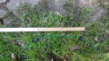
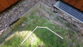
Auf dem Rückweg zu Ladestation kann es sein, dass der Mower an einer Stelle auf das Perimeter fährt, so dass er den gesamten Perimeterdraht bis zur Ladestation abfahren muss. Um diesen Weg zu verkürzen, gibt es die schnelle Rückkehr. Der Anwender muss dazu das Perimeterkabel so verlegen, dass es ein Viereck ergibt. Diese Viereck wird dann vom Roboter beim Perimetertracking erkannt. Wenn er das Viereck erkannt hat, dreht er sich um 90 Grad vom Perimeter weg in den Innenbereich, und fährt auf die andere Seite des Rasens. Wenn er dort das Perimeterkabel entdeckt, nimmt er von dieser Stelle das Perimetertracking wieder auf.
Für das Viereck hat sich folgende Abmessung als günstig herausgestellt. Es kommt allerdings auch auf die Abmessungen des Mowers an. Der Mower sollte bei dem Tracking in den Drehmodus kommen. Drehen bei der ersten Linkskurve. Dann drehen bei der nächsten Rechtskurve. Dann Linkskurve fahren. [Video:https://youtu.be/ipdVJzQn5Tc]
Das Viereck kann auf zwei Arten verlegt werden. Einmal mit Ecken und einmal mit abgeflachten Ecken. Die Abgeflachten Ecken sind dazu da, dass der Mower an der Ecke besser erkennt, in welche Richtung er sich vom Perimeter wegdrehen soll, wenn er fast parallel zum Perimeter fährt. Dadurch ist die Perimeternahe Spule als erstes draußen und er dreht vom Perimeter weg anstatt zum Perimeter hin. Das ist notwendig, falls hinter dem Perimeter ein Beet kommt in das sich der Mower reindrehen könnte.


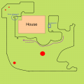
Beispiel, wie ich meine Vierecke angebracht habe

Die Erkennung ist abhängig von der Position der Spulen und vom Abstand der Spulen zum Antriebsrad.
Die Implemetierung steht in der Datei: bPerimeterTracking.h Klasse: class TfindTriangle : public Node
Die Erkennung erfolgt anhand des jeweils gedrehten Winkels. Sie wurde mit einer Statemachine umgesetzt.
Den Ablauf der Statmachine und die berechneten Winkel kann man sich mit dem Befehl bht.tri anzeigen lassen.
bht.tri
Die entsprechenden Winkel und maximal Distanzen muss man dann im Code in der Klasse: class TfindTriangle anpassen. Im Folgenden die leicht ausgedünnte Klasse um einen besseren Überblick zu bekommen. Die Zeilen errorHandler.setInfoNoLog(..) sind die Ausgabe, wenn der Befehl bht.tri aktiviert wurde. Diese wurden hier mit aufgeführt um die Ausgabe besser interpretieren zu können.
 virtual NodeStatus onUpdate(Blackboard& bb) {
   ...
Der gefahrene Winkel wird vor dem Case Statement alle 500ms ermittelt.
   //============================================
   // Calculate driven angle every 500ms.
   //============================================
   if (millis() - lastRunAngleCalculation >= 500) {
     lastRunAngleCalculation = millis();
     ...
     angle = (cmL - cmR)  * 57.2957795f / CONF_DISTANCE_BETWEEN_WHEELS_CM;
     if (flagShowFindTriangleStates) {
       errorHandler.setInfoNoLog(F("Winkel: %f cmL %f cmR %f\r\n"), angle, cmL, cmR);
     }
   }
Abfrage der States
   // Check for left curve / right curve / second left curve
   switch (state)
   {
Im case 0 wird nach eine Linkskurve gesucht. Ein negativer Winkel bedeutet eine Linkskurve/-drehung. Wenn der Winkel z.B. <-25 Grad ist, wurde diese gefunden und es wird in den case 1 geschaltet.
   case 0:  // search for left curve
     if (angle < -25) {
       if (flagShowFindTriangleStates) {
         errorHandler.setInfo(F("!03,s0 set state = 1 Left turn found angle: %f ms: %lu\r\n"), angle, millis());
       }
       bb.motor.startDistanceMeasurementTriangle();
               ...
       state = 1; // Activate triangle searching
     }
     break;
In case 1 wird ständig überprüft, ob eine bestimmte Strecke nach der Linkskurve überschritten wurde. Im Beispiel 55cm. Wenn ja, ist das zu weit und es wird wieder zurück in den case 0 gesprungen, da es nicht sein kann, das das Dreieck so lang ist. Wenn innerhalb der Strecke von 55cm dann ein Winkel > 50 gefunden wurde, wird in den case 2 gesprungen. Ein positiver Winkel bedeutet eine Rechtskurve/-drehung.
   case 1: // search for right turn
     distance = bb.motor.getDistanceInCMForTriangle();
     if (distance > 55) {
       state = 0;
       if (flagShowFindTriangleStates) {
         errorHandler.setInfo(F("!03,s1 set state = 0 distance %f > 55 ms: %lu\r\n"), distance, millis());
       }
     }
     else if (angle > 50) {
       if (flagShowFindTriangleStates) {
         errorHandler.setInfo(F("!03,s1 set state = 2 angle %f distance %f < 50\r\n"), angle, distance);
       }
       bb.motor.startDistanceMeasurementTriangle();
       ...
       state = 2;
     }
     break;
In case 2 wird als erstes wieder die gefahrene Distanz nach dem Rechtswinkel überprüft. Solange die Distanz von 50 cm nicht überschritten wurde, wird auf eine Linkskurve geprüft. Wenn der Winkel <-25 Grad ist, wurde diese erkannt und es wird in den State 3 gesprungen.
   case 2:  // search for second left curve
     distance = bb.motor.getDistanceInCMForTriangle();
     if (distance > 50) {
       state = 0;
       if (flagShowFindTriangleStates) {
         errorHandler.setInfo(F("!03,s2 set state = 0 distance %f > 50 ms: %lu\r\n"), distance, millis());
       }
     }
     else if (angle < -25) {
       if (flagShowFindTriangleStates) {
         errorHandler.setInfo(F("!03,s2 set state = 3 angle %f distance %f < -25\r\n"), angle, distance);
       }
       bb.motor.startDistanceMeasurementTriangle();
        ...
       state = 3;
     }
     break;
Case 3 gibt BH_SUCCESS an den BHT zurück und es wird auf die andere Seite des Rasens gefahren.
   case 3:
     if (flagShowFindTriangleStates) {
       errorHandler.setInfo(F("!03,s3 set state=0  Cross Lawn Activated\r\n"));
     }
     state = 0;
     return BH_SUCCESS;
     break;
      ...
   }
   return BH_RUNNING;
 }
Testen des Algorithmus: Den Roboter auf den Perimeter stellen, so das die linke Spule außen ist und die rechte Spule innen. Mit dem Befehl
tpt //test perimeter tracking to dock. Mower stands on perimeter
das Perimetertracking starten.
Mit dem Befehl
bht.tri
die Ausgabe der Viereckserkennung starten. (tri steht für triangle, da vorher wurde ein Dreieck zur Erkennung verwendet wurde)
Mähzonen zwischen aneinander liegenden Flächen
Mähzonen können eingerichtet werden zwischen aneinander liegenden Flächen die eine direkte Verbindung haben. Dazu wird das Perimeterkabel zwischen den Flächen in einem Abstand von ca. 13cm verlegt. Es wird eine Lücke von ca. 30cm zu dem gegenüberliegenden Perimeterkabel gelassen. Dadurch ist die Wahrscheinlichkeit geringer, dass der Roboter auf die andere Fläche fährt.
Siehe Bild:
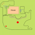
Beispiel, Mähzonenabgrenzung
Abmessungen


(Im obigen Bild ist es normal nicht notwendig Mähzonen einzurichten, da der Roboter durch den Algorithmus relative gut alle Bereiche des Rasens abdeckt.)
Der Abstand des Bereichsabgrenzungskabels zum gegenüberliegenden Perimeterkabel (hier 30cm Abstand) kann durch Tests optimiert werden. Der Abstand hängt von der Funktionalität des Perimetertracking ab. Zum einen von der Position der linken Spule beim Tracken des gebenüberliegenden Kabels, sowie das Tracking des Bereichsabgrenzungskabels selber.
In der config.h sollte die Konstante CONF_USE_ZONE_RECOGNITION auf true gesetzt werden.
#define CONF_USE_ZONE_RECOGNITION true
Da der Roboter voreingestellt mit den Spulen ca. 20cm über das Kabel fährt, kann es sein, dass er mit den Spulen dann innerhalb des nächsten Bereichs stehen bleibt. Wenn CONF_USE_ZONE_RECOGNITION false ist, würde der Roboter einfach weiterfahren, da er ggf. eine Ecke überfahren hat. Wenn CONF_USE_ZONE_RECOGNITION true ist, wird nach dem Überfahren geprüft, ob beide Spulen wieder innerhalb des Perimeters sind. Falls ja, wird mindestens eine Strecke von (-CONF_PERIMETER_DRIVE_BACK_CM-10) zurückgefahren. Also 10cm mehr als sonst CONF_PERIMETER_DRIVE_BACK_CM zurückfahren würde.
Das Anfahren eines Bereiches aus der Ladestation heraus erfolgt mit dem Befehl:
area,x //wobei x der zurückzulegende Weg in m ist.
Wurde die angegebene Strecke x am Perimeter zurückgelegt, fängt der Mower an zu mähen.
Die gefahrene Distanz auf dem Perimeter kann mit dem Befehl
show.distance
angezeigt bzw. gemessen werden.
Achtung: Man sollte sich genau merken, wo die Kabel für die Mähzonenabgrenzung liegen für den Fall, dass der Rasen vertikutiert wird.
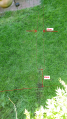
Verlegung des Perimeterkabels an Ecken
Der Mower bestimmt in welcher Richtung er sich am Perimter dreht anhand der zuerst rausgefahrenen Spule. Daher ist es wichtig die Ecken nicht im 90 Grad Winkel zu verlegen. Wenn der Mower z.B, mit der rechte Spule nahe am Perimeter langfährt und dann an der Ecke rausfährt, sollte auch die rechte Spule als erstes aus dem Perimeter fahren.
In den folgenden Bildern sind drei Beispiele zu sehen, wie Ecken verlegt werden sollten.
Außenecke
Außenecke
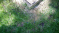
Innenecke


Perimeter Sender
Es wir die original Ardumower Sender Hardware verwendet. Die Software wurde etwas abgeändert. Es wird ein 128 Bit Signal gesendet.
Folgendes Perimetersignal wird gesendet:
1, 1, -1, -1, -1, 1, -1, -1, 1, -1, 1, -1, -1, 1, 1, -1, 1, 1, -1, -1, 1, 1, -1, 1, 1, -1, 1, -1, 1, -1, -1, 1, -1, -1, 1, -1, 1, 1, -1, 1, -1, 1, -1, 1, -1, 1, 1, -1, -1, 1, 1, -1, -1, 1, 1, -1, 1, -1, 1, 1, -1, -1, 1, -1,
-1, 1, 1, -1, 1, 1, -1, -1, 1, -1, -1, 1, -1, 1, -1, 1, 1, -1, 1, -1, -1, 1, -1, -1, 1, 1, -1, 1, -1, -1, 1, 1, -1, 1, -1, 1, -1, 1, -1, 1, -1, 1, 1, -1, -1, 1, -1, -1, 1, -1, 1, -1, -1, 1, -1, -1, 1, 1, -1, 1, 1, -1, -1, 1
Die LEDs haben folgende Funktion (von links nach rechts):
- 1. 12V vorhanden
- 2. 5V vorhanden
- 3. Grün wenn der Interrupt läuft, der das Signal sendet ( rote LED nicht verfügbar). Aus wenn geladen wird.
- 4. Grün wenn ein Strom durch den Perimeter fließt, rot wenn keine Strom fließt (Perimeter unterbrochen) oder sehr wenig Strom. Aus wenn geladen wird.
- 5. Gelb der Roboter wird geladen. Perimetersignal ist ausgeschaltet.
Achtung: die LEDs 3 und 4 sind Duo LEDs. D.h. diese haben zwei Farben. Bei LED 3. ist die rote LED nicht ansprechbar, da auf dem Nano der falsche Pin hardwaretechnisch connected wurde. Desweiteren, können die LEDs falsch herum eingelötet worden sein. Dann wundert man sich z.B., dass LED 4. rot ist obwohl alles in Ordnug ist und ein Strom fließt. Oder eben LED 3. rot anzeigt, obwohl ich hier grün geschrieben habe.
Wenn der Sender an ist und der Roboter kehrt nach zwölf Stunden nicht in die Ladestation, schaltet der Sender das Signal ab. Dann entweder den Sender neu starten, oder den Roboter in der Ladestation laden.
Troubleshooting
Mower bleibt stehen
Problem: Mower blieb stehen, Ursache war wohl der Sender. Da leuchteten nur noch die beiden linken LEDs. Sender ausgeschaltet und wieder eingeschaltet, 4 LEDs wieder auf grün und dann ging es wieder.
Lösungsvorschlag: Die dritte grüne Leuchte von links zeigt an, ob der Sender Interrupt im Nano läuft.
Möglichkeit a) Der Sender ist länger als 3h an, ohne das der Roboter wieder in die Station zurückgekehrt ist. Dann schaltet der Sender das Perimetersignal ab.
Möglichkeit b) Da diese nicht an war scheint sich der Nano aufgehängt zu haben. Falls das noch mal passiert, würde ich den China Nano gegen einen original Arduino Nano austauschen. Da die Software bei mir seit einem Jahr läuft, gehe ich nicht davon aus, das diese die Ursache ist. Ich hatte vorher billige Nanos verwendet. Die waren bei mir nicht wirklich Frequenzstabil, was für den Sender aber notwendig ist. Nun habe ich einen Originalen drin.
Ich bekomme diese Meldung: Out: READ und In: CMD
Problem: In Arduino Central wird folgendes angezeigt:
Out: READ
In: CMD: Command not recognized.
Out: READ
In: CMD: Command not recognized.
Out: READ
In: CMD: Command not recognized.
Out: READ
Lösungsvorschlag: In den Arduino Central Settings ist "Read Command -> Enable Read Command" eingeschaltet
Understanding the Behaviour Tree
Die Beschreibung steht ausschließlich in Englisch zur Verfügung.
- REDIRECT Understanding the Behaviour Tree