Sensor fusion
Inhaltsverzeichnis
Sensor errors
Odometry sensor

After a time, the odometry's error accumulates, and the course (Degree) and position (x/y) are getting unprecise.
Typical errors in outdoor condition (wet lawn, high slope):
- Distance: 20cm per meter
- Course: 10 degree per meter
The course can be permanently corrected by the compass sensor, the position by recalibration on the perimeter wire.
Sensor fusion
- Calculation of short-time position by Odometry and Compass
- Calculation of long-term position via GPS

A Kalman filter can be used to fuse all sensor values.
Position recalibration
Because odometry error increases over time, the robot needs to periodically recalibrate its exact position (get the error to zero). This works by detecting its exact position on the perimeter wire (using cross correlation).
- Learn mode: robot completely tracks perimeter wire once and saves course (degree) and distance (odometry ticks) in a list (perimeter tracking map).
- Position detection: robot starts tracking the perimeter wire at arbitrary position until a high correlation with a subtrack of the perimeter tracking map is found. There it can stop tracking and knows its position on its perimeter tracking map.

Mapping and localization (SLAM)
The perimeter magnetic field could be used as input for a robot position estimation. However, as both the magnetic field map and the robot position on it is unknown, the algorithm needs to calculate both at the same time. Such algorithms are called 'Simultaneous Localization and Mapping' (SLAM).
Input to SLAM algorithm:
- control values (speed, steering)
- observation values (speed, heading, magnetic field strength)
Output from SLAM algorithm:
- magnetic field map (including perimeter border)
- robot position on that map (x,y,theta)
Example SLAM algorithms:
- Particle filter-based SLAM plus Rao-Blackwellization: model the robot’s path by sampling and compute the 'landmarks' given the poses
Lane-by-lane mowing
In the lawn-by-lane mowing pattern, the robot uses a fixed course. When hitting an obstacle, the new course is added by 180 degree, so that the robot enters a new lane.
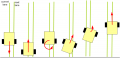
Robot turns 180 degree and enters a new lane

Simulation
Here's [1] a simulation of localization using odometry sensors.
