Soldering The Sender: Unterschied zwischen den Versionen
Aus www.wiki.ardumower.de
Roland (Diskussion | Beiträge) |
Roland (Diskussion | Beiträge) |
||
| Zeile 1: | Zeile 1: | ||
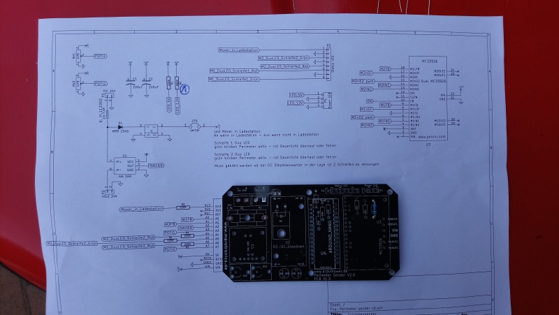
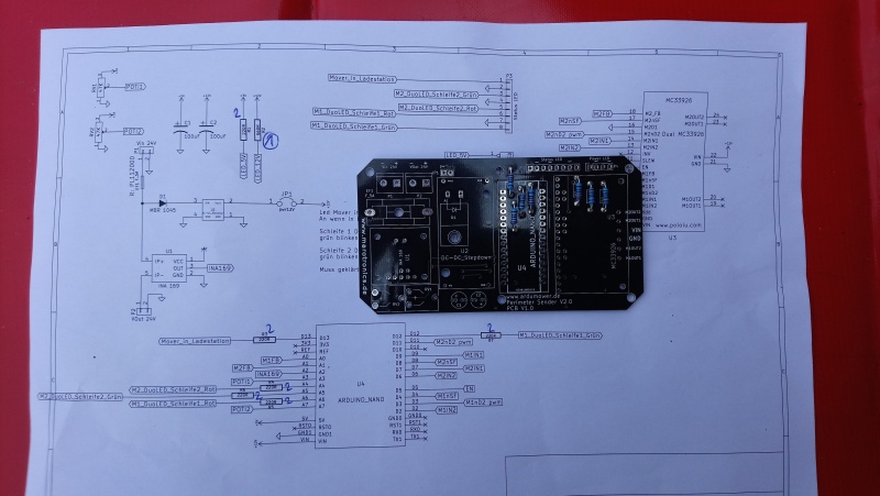
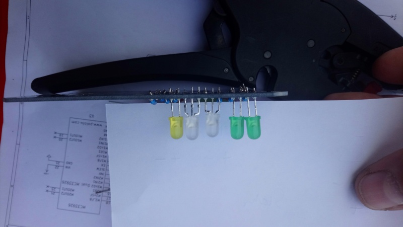
| + | The soldering of the sender will be described. | ||
| + | The potentiometers will not be soldered because they have no function. If you want to install them you can do this. | ||
| + | |||
[[File:SenderSoldering1.JPG|none|thumb|Solder 560 Ohm resistor|800px]] | [[File:SenderSoldering1.JPG|none|thumb|Solder 560 Ohm resistor|800px]] | ||
| Zeile 25: | Zeile 28: | ||
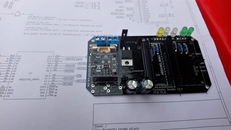
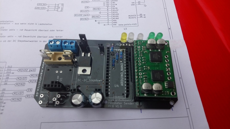
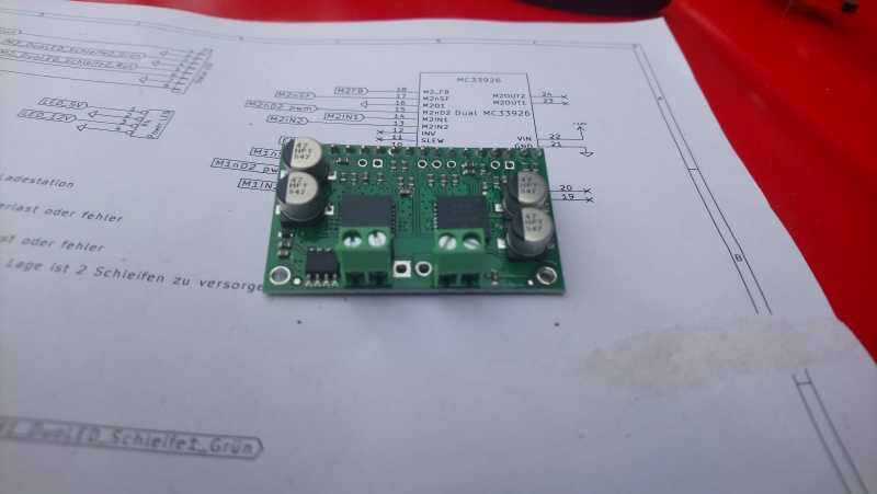
[[File:SenderSoldering24.JPG|none|thumb|Install the motor driver and solder it. Solder also the two right pins. I didn't it here because I want to connect a second external power supply|800px]] | [[File:SenderSoldering24.JPG|none|thumb|Install the motor driver and solder it. Solder also the two right pins. I didn't it here because I want to connect a second external power supply|800px]] | ||
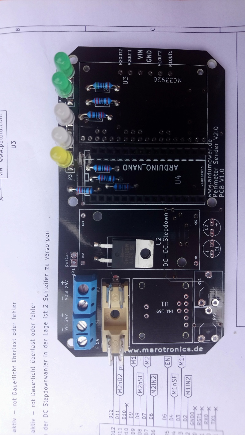
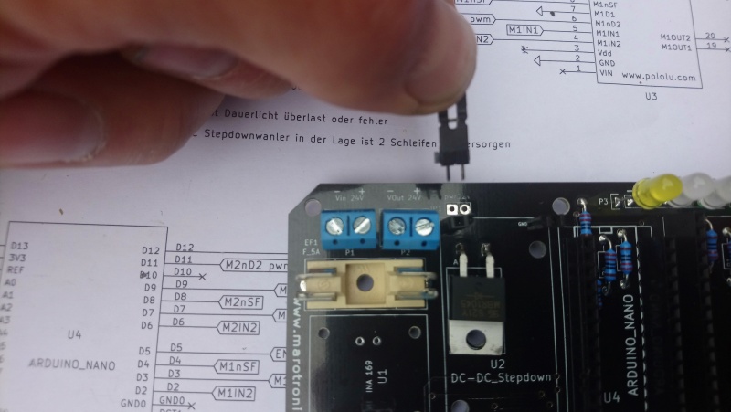
[[File:SenderSoldering25.JPG|none|thumb|Solder the terminal blocks. You have two pins soldered between the terminal blocks |800px]] | [[File:SenderSoldering25.JPG|none|thumb|Solder the terminal blocks. You have two pins soldered between the terminal blocks |800px]] | ||
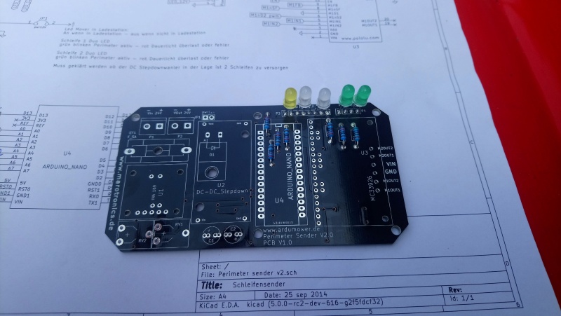
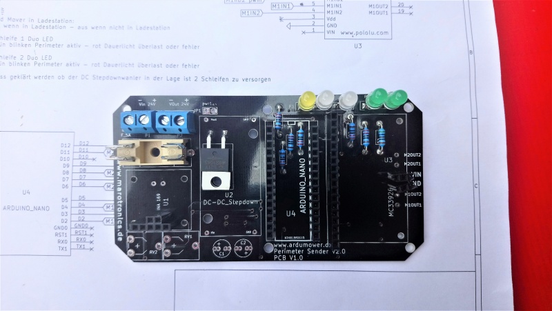
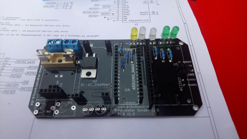
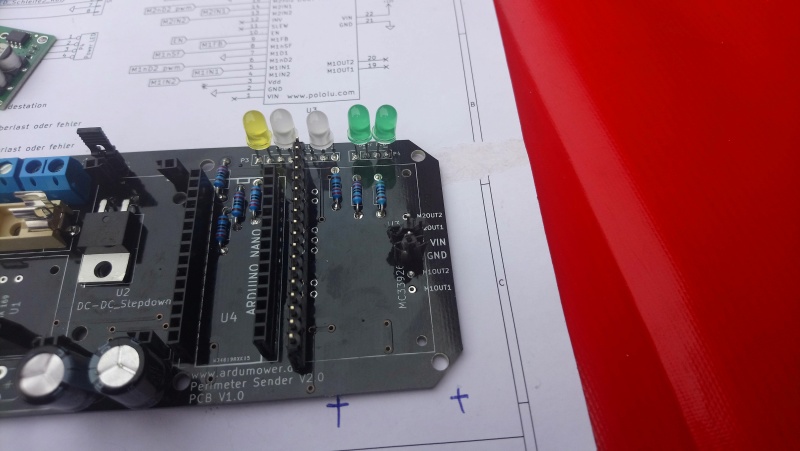
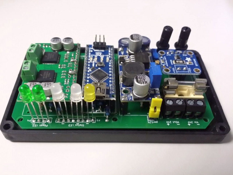
| − | [[File: | + | [[File:Ardumower sender pcb.jpg|none|thumb|Board with all components|800px]] |
Version vom 10. Juni 2018, 14:25 Uhr
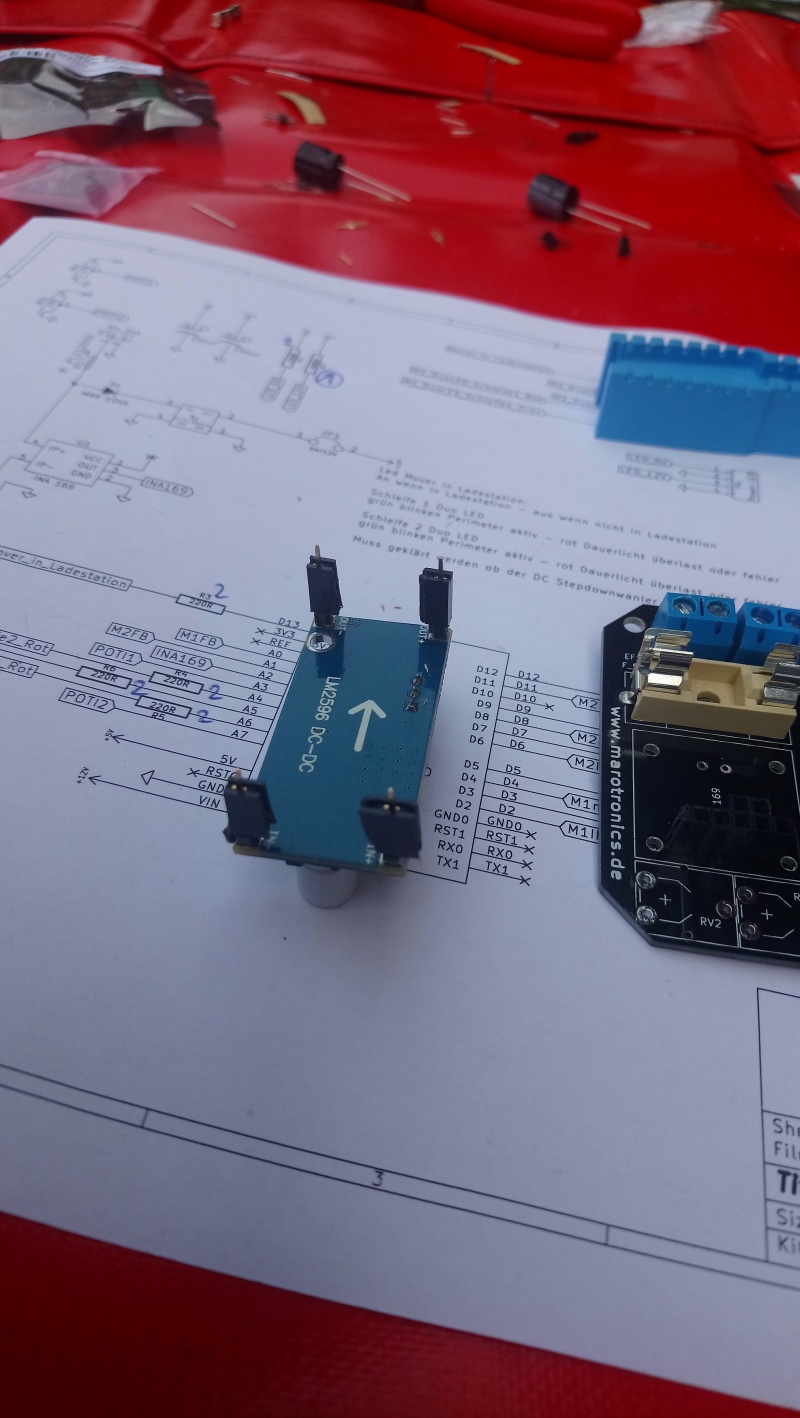
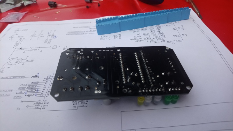
The soldering of the sender will be described. The potentiometers will not be soldered because they have no function. If you want to install them you can do this.
