The soldering of the sender will be described.
The potentiometers will not be soldered because they have no function. If you want to install them you can do this.

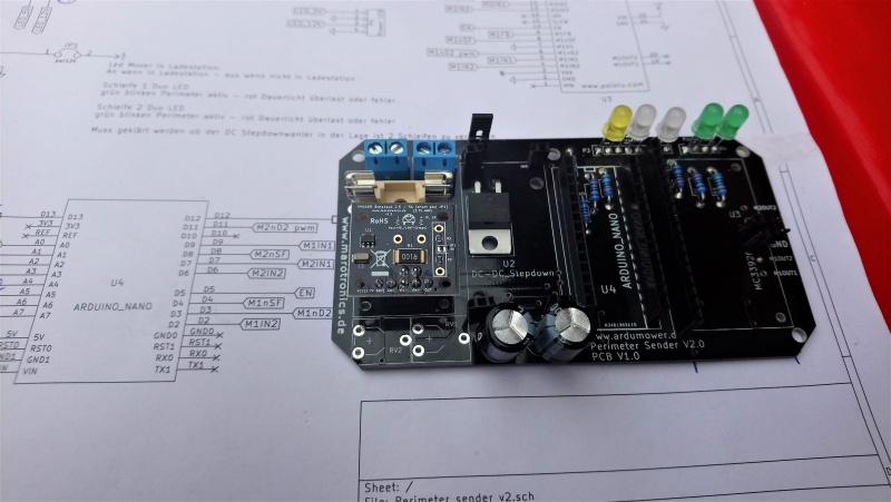
Diodes with correct plug in direction
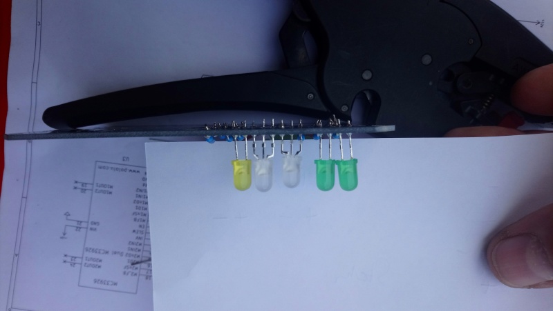
Diodes with correct plug in direction
Diodes with correct plug in direction

Cut the socket strip at a pin not in between
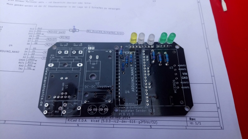
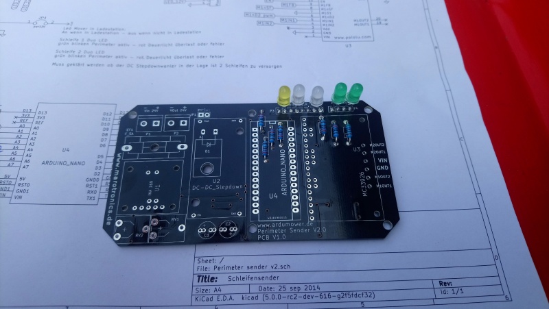
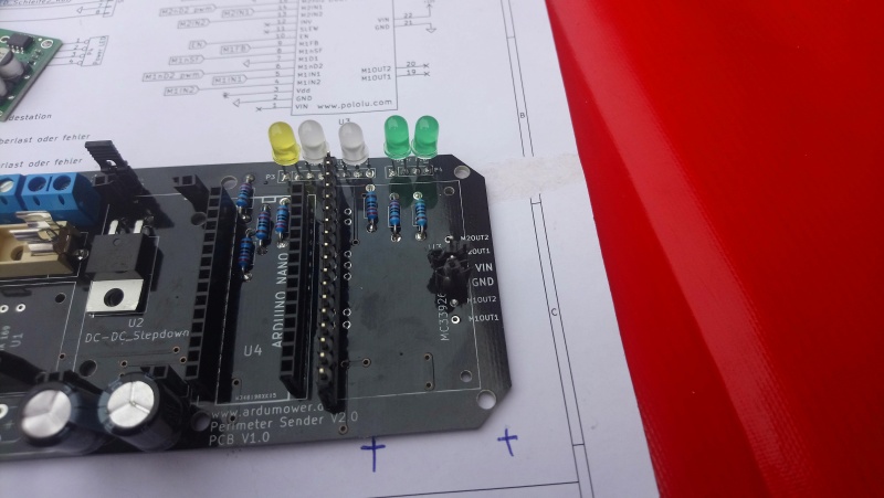
Solder the socket strips for the nano

Solder the terminal blocks
Solder socket strips for INA and mc33926 motor drive
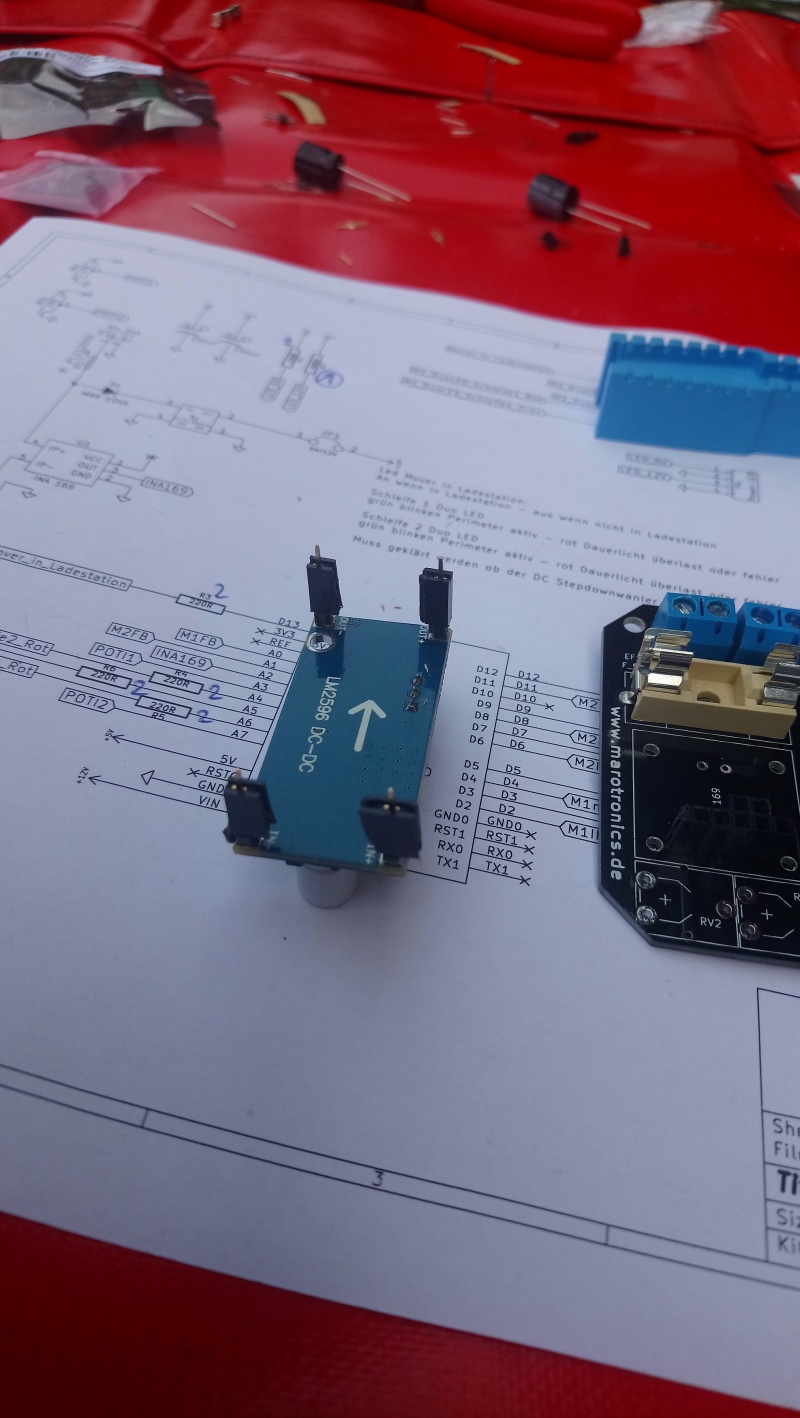
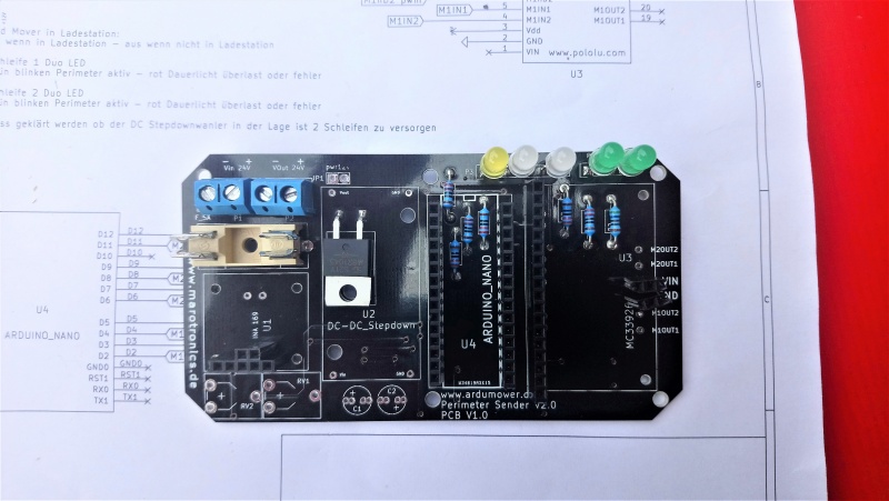
Solder pins to DC/DC converter and then put a socket on

Put the DC/DC converter on the board
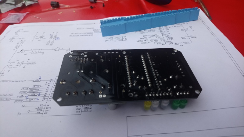
Flip the board and solder the sockets
Sockets for DC/DC converter soldered
Put in the pins for the INA
Install the INA and solder it
Put in the pins fot the mc33926 motor drive
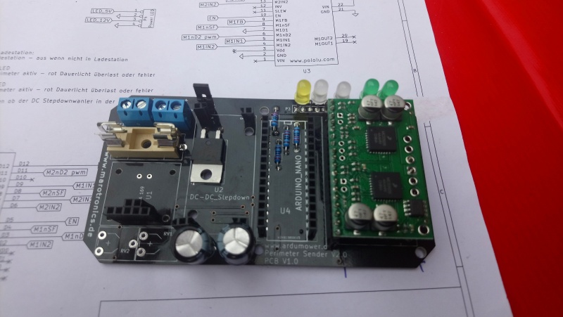
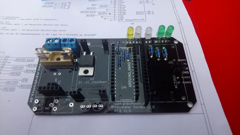
Install the motor driver and solder it. Solder also the two right pins. I didn't it here because I want to connect a second external power supply
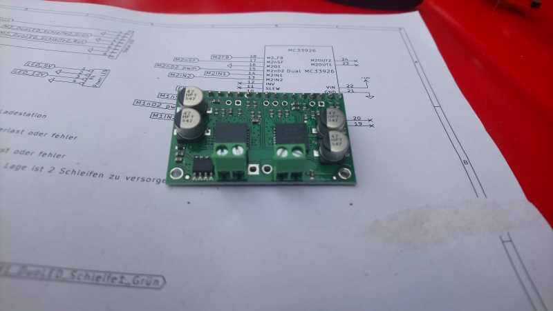
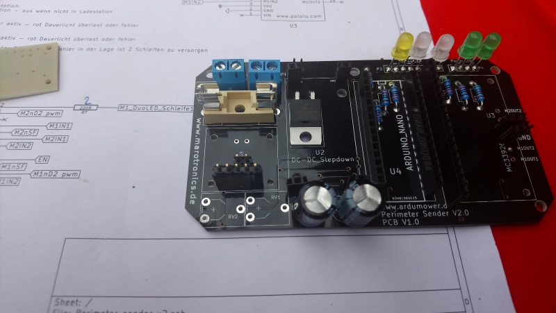
Solder the terminal blocks. You have two pins soldered between the terminal blocks
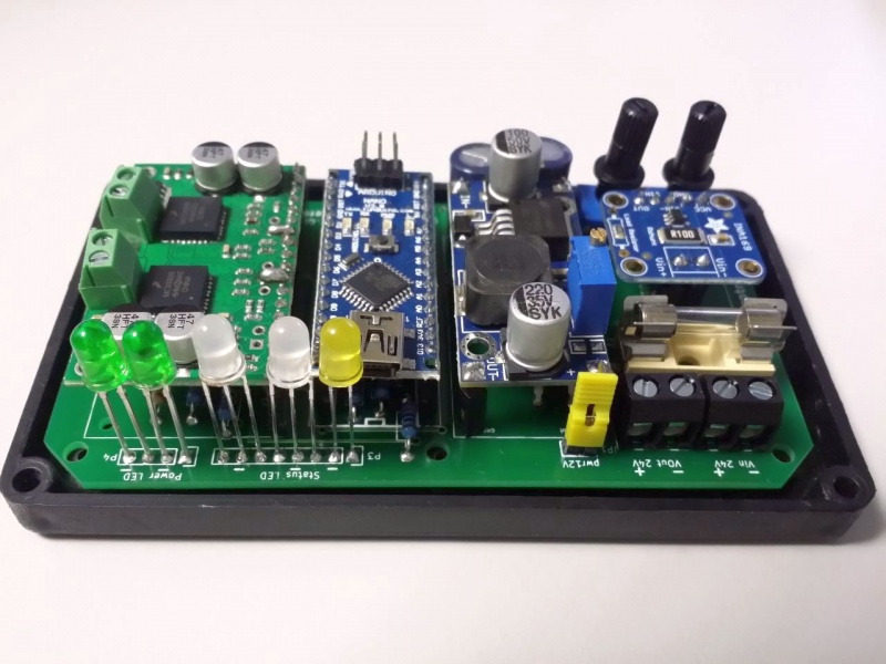
Board with all components

Three terminalblocks installed on the motor driver because I want to use a second external powersupply for the perimeter signal


