Ultrasonic: Unterschied zwischen den Versionen
Aus www.wiki.ardumower.de
(→Ultrasonic Sensor) |
(→Wiring) |
||
| Zeile 19: | Zeile 19: | ||
== Wiring == | == Wiring == | ||
| − | + | Ultrasonic Module VCC (+5V) — PCB VCC (+5V) | |
| − | + | Ultrasonic Module GND — PCB GND | |
| − | + | Ultrasonic Module Trigger — PCB Digital Pin | |
| − | + | Ultrasonic Module Echo — PCB Digital Pin | |
| − | Ultrasonic Module VCC (+5V) — | + | |
| − | + | ||
| − | Ultrasonic Module GND — | + | |
An internal schematics of the sensor can be found here.[http://uglyduck.ath.cx/ep/archive/2014/01/Making_a_better_HC_SR04_Echo_Locator.html] | An internal schematics of the sensor can be found here.[http://uglyduck.ath.cx/ep/archive/2014/01/Making_a_better_HC_SR04_Echo_Locator.html] | ||
Version vom 30. Mai 2016, 00:47 Uhr
Ultrasonic Sensor
An ultrasonic sensor is an excellent way to detect obstacles.
Example: HC-SR04
Distance 2 to 450 cm
Current 15 mA
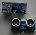
HC-SR04
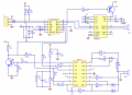
HC-SR04 schematics


Wiring
Ultrasonic Module VCC (+5V) — PCB VCC (+5V) Ultrasonic Module GND — PCB GND Ultrasonic Module Trigger — PCB Digital Pin Ultrasonic Module Echo — PCB Digital Pin
An internal schematics of the sensor can be found here.[1]