WIFI Perimeter Sender(English): Unterschied zwischen den Versionen
Aus www.wiki.ardumower.de
(→Hardware connecting) |
(→Hardware connecting) |
||
| Zeile 4: | Zeile 4: | ||
You need : | You need : | ||
| − | ESP32 DEV KIT V1 (or later but with same pin diagram). | + | 1 ESP32 DEV KIT V1 (or later but with same pin diagram). |
| − | [[Datei: | + | [[Datei:Esp32-1.jpg|200px]] [[Datei:Esp32-2.jpg|200px]] [[Datei:esp32 layout.png|600px]] |
| − | |||
| + | 1 INA3221 3-Channel DC Current Sensor : | ||
| − | + | [[Datei:INA3221.jpg|200px]] | |
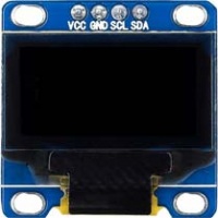
| − | + | 1 I2C Small OLED Display | |
| − | L298N motor Driver. | + | [[Datei:OLED-Display-1.jpg|200px]] |
| + | |||
| + | |||
| + | 1 DC/DC Converter | ||
| + | |||
| + | [[Datei:DC_DC converter.jpg|200px]] | ||
| + | |||
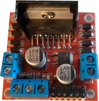
| + | 1 L298N motor Driver. | ||
| + | |||
| + | [[Datei:L298N-1.jpg|200px]] | ||
---- | ---- | ||
Version vom 14. März 2021, 09:36 Uhr
WIFI Perimeter sender.
Hardware connecting
You need :
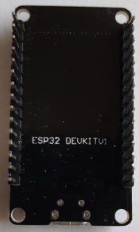
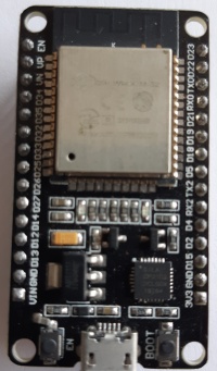
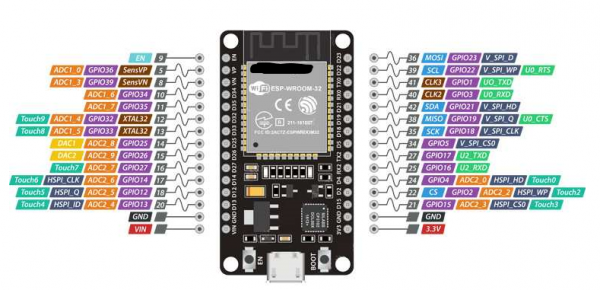
1 ESP32 DEV KIT V1 (or later but with same pin diagram).
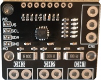
1 INA3221 3-Channel DC Current Sensor :
1 I2C Small OLED Display
1 DC/DC Converter
1 L298N motor Driver.
ESP32 DEV KIT replace the bluetooth module HC05 to communicate with PCB1.3, so you can build a small PCB to connect all wire, or order some of them from JLCPCB for example (The same board is also use to build the WIFI sender.)
