PCB 1.2 (English)

This page describes how to assemble the Ardumower PCB, flash the Arduino and configure the robot mower.
Inhaltsverzeichnis
Abstract
The controller is built around a ready microcontroller board (Arduino Mega 2560 using 54 I/O pins).
Components overview
Ardumower PCB connects all modules (available in the shop)
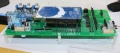
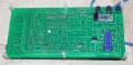
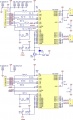
PCB top
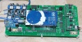
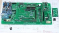
PCB back
PCB and MC33926


Needed modules
All modules can be purchased as complete kits via the shop ![]() .
.
PCB
The printed circuit board (PCB) connects all electronic modules. The PCB is made with the following design parameters:
- PCB dimensions 241x114mm
- All modules (motor driver, Bluetooth, etc.) can be soldered (or plugged) on the PCB (modules are available in the Ardumower shop)
- Uses the Arduino Mega 2560
- Optional: can use Arduino Due via additional adapter PCB
- Optional: integrated charging circuit (current limiting)
- All connections are available on connectors as well as +5V and GND
- Max. trace current (for motors): 8A
PCB building manual
Robot PCB v0.5 (initial prototype, please do not use anymore)
Robot PCB v1.2 (minor layout changes)
- Schematics
- Photos
- Build instructions
- Build instructions (English translation)
- WorkaRound20150527
- WorkaRound20150530
- also see: Documentation in Github
NOTE: The schematics and PCB files were created with KiCad. They can be downloaded from github and can be edited by open source KiCAD software (Download here or here).
PCB building videos
- Resistors
- Diodes and relay
- Capacitors and transistors
- Piezo buzzer and fuse
- Strip pins
- DC/DC converter
- RTC module
- Dual MC33926
- INA169
- Battery & charger
PCB jumpers
| Feature used | YES | NO | Comment |
|---|---|---|---|
| Integrated charging control via adjustable
voltage regulator (LM350T) with potentiometer for adjustable charging voltage (recommended: NO) |
D7: DIODE
D3: DIODE C1, C4, U4, RV1: used |
D7: SHORT-CIRCUIT
D3: SHORT-CIRCUIT C1, C4, U4, RV1: not used |
Do not use if using external battery charger |
| External power while charging (recommended: NO) | JP6: CLOSE
JP7: OPEN D4: DIODE C5: not used |
JP6: OPEN
JP7: CLOSE D4: SHORT-CIRCUIT C5: used |
Use to power your PCB from externally (disconnect battery from PCB) while charging |
| Arduino controlled charge relay (recommended: YES) | JP4: CLOSE
JP5: OPEN |
JP4: OPEN
JP5: CLOSE |
Use for Arduino controlled charge relay (not automatic charging) |
| Arduino Due (3.3V I/O) | LP0, ..., LP15: OPEN | LP0, ..., LP15: CLOSE | Do not use if using Arduino Mega |
| Bluetooth VCC=3.3V | JP8: OPEN
JP9: CLOSE |
JP8: CLOSE
JP9: OPEN |
Many latest modules use 3.3V |
| Bluetooth programming mode | JP2: CLOSE | JP2: OPEN | Use for reprogramming baud rate etc. |
PCB modules

| Module | Feature | Pinout | Optional | Comment |
|---|---|---|---|---|
| U1 | DC/DC converter (10V) | GND, Vout, Vin, GND | No | |
| U2 | Bluetooth (HC-05) | VCC, GND, TXD, RXD, Key, LED | Yes | |
| U3 | Current sensor (charging) | VCC, GND, OUT, IP+, IP-5 | Yes | |
| U4 | Charge control (LM350T) | AJD, OUT, IN | Yes | |
| U5 | Current sensor (charging) | VCC, GND, OUT, IP+, IP-5 | Yes | |
| U6 | DC/DC converter (3.3V) | GND, Vout, Vin, GND | No | |
| U7 | DC/DC converter (5V) | GND, Vout, Vin, GND | No | |
| U8 | Realtime clock (DS1307) | Batt, GND, VCC, SDA, SCL, DS, SQ | Yes | |
| U9 | Wifi (ESP8266) | TX, CH_PD, Reset, VCC, GND, GP_IO2, GP_IO0, RX | Yes | |
| U10 | Level shifter 5V->3V (Arduino Due) | Yes | ||
| U11 | Wifi (ESP8266) | TX, CH_PD, Reset, VCC, GND, GP_IO2, GP_IO0, RX | Yes | alternative mount position |
PCB connectors
| Connector | Feature | Pinout | Optional | Comment |
|---|---|---|---|---|
| P1 | Sonar center (HC SR-04) | 5V, GND, Trigger, Echo | Yes | |
| P2 | Sonar right (HC SR-04) | 5V, GND, Trigger, Echo | Yes | |
| P3 | Sonar left (HC SR-04) | 5V, GND, Trigger, Echo | Yes | |
| P4 | reserved | Yes | ||
| P5 | IMU (gyro,acceleration,compass) (GY-80) | Yes | ||
| P6 | Lawn sensor | Yes | ||
| P7 | Status LEDs | Yes | ||
| P8 | Odometry right | Yes | ||
| P9 | Odometry left | Yes | ||
| P10 | GPS (GY-NEO6MV2) | Yes | ||
| P11 | Bumper | GND, GND, right, left | Yes | |
| P12 | Perimeter coil (center or left) | 5V, GND, perimeter | Yes | |
| P13 | R/C remote control | 5V, GND, mow, steer, speed, switch | Yes | |
| P14 | Measurement points | 5V, GND, (Depending on JP15: 3.3V, 5V or Arduino 3.3V) | Yes | |
| P15 | Wheel motor left | M1OUT1, M1OUT2 | No | |
| P16 | Optional motor driver input | Yes | Do not connect | |
| P17 | Optional motor driver input | Yes | Do not connect | |
| P18 | Wheel motor right | M2OUT1, M2OUT2 | No | |
| P19 | Tilt sensor | 5V, GND, tilt | Yes | |
| P20 | Button (Start/Stop) | No | ||
| P21 | Drop sensor right | Yes | ||
| P22 | Reserved | Yes | ||
| P23 | Reserved | Yes | ||
| P24 | Reserved | Yes | ||
| P25 | Reserved | Yes | ||
| P26 | Reserved | Yes | ||
| P27 | Reserved | Yes | ||
| P28 | Reserved | Yes | ||
| P29 | Reserved | Yes | ||
| P30 | Perimeter coil right | Yes | ||
| P31 | Drop sensor left | Yes | ||
| P32 | GND | Yes | ||
| P33 | 5V | Yes | ||
| P34 | 3.3V | Yes | ||
| P35 | Mower motor RPM | Yes | ||
| P36 | Reserved | Yes | ||
| P37 | Mower motor | No | ||
| P38 | Reserved | Yes | ||
| P39 | Reserved | Yes | ||
| P40 | User switches | Yes | ||
| P41 | Rain sensor | Yes | ||
| P42 | Charging pins | Yes | ||
| P43 | Battery (24V) | No | ||
| P44 | Wifi module (ESP8266) | Yes | ||
| P45 | Reserved | Yes | ||
| P46 | Reserved | Yes |
Power supply
Please also read the section 'Voltages' under Motor driver for more information on motor voltages.
It is recommended to use a voltage step-down converter (e.g. module using LM2596) to generate the 5V voltage for the Arduino and all additional modules. Before connecting, set the voltage of the converter to 5V.
![]() Warning : never connect more than 5V on the Arduino 5V pins, or you will damage the Arduino. Therefore, always measure the 5V voltage before connecting it to the Arduino 5V pin!
All components together (as shown in the schematics) need about 5W power.
Warning : never connect more than 5V on the Arduino 5V pins, or you will damage the Arduino. Therefore, always measure the 5V voltage before connecting it to the Arduino 5V pin!
All components together (as shown in the schematics) need about 5W power.
Abstract
Ardumower uses two different types of motors (all motors can be purchased via the shop ![]() ):
):
- Two motors (with integrated gearing) for driving (wheel motors) and with integrated encoders (for distance and speed control)
- One motor (with high rotation speed) for mowing (mower motor)
To control the motors, it requires motor drivers. In addition, the motor driver measures the motor current, and allows us to detect obstacles as motor current increases at obstacles. Ardumower uses two dual MC33926 motor drivers, so two channels for left and right motor and two dual channels (connected in parallel) for the mowing motor.
It is not safe to connect motors directly to the motor driver. Especially, when quickly turning motors from forward to reverse (or vice verse), high voltage spikes appear, and these could damage the motor drivers in the long run. Therefore, we developed driver protector boards that are connected between motor driver and motor.

Voltages
As in all modern systems, Ardumower uses 24V motors.
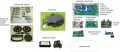
Motor driver assembly (dual MC33926)
Motor driver features: up to 3A with integrated current sensor and thermal shut-down protection
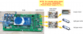
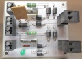
PCB, MC33926, protector and motors
PCB and MC33926
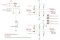
MC33926 pinout
MC33926 schematics


For wiring of motor drivers, protector and motors, please open manual in section Protector PCB.
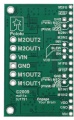
Protector PCB
![]() When quickly tunring motors from forward to backward (or vice versa), high voltage spikes appear. These high voltage spikes could damage the motor driver in the long run. To eliminate high voltage spikes, it is adviced to use a Protector board between motor driver and motor. Two Protector PCBs are required, one for the gear motors, and one for the mowing motor.
When quickly tunring motors from forward to backward (or vice versa), high voltage spikes appear. These high voltage spikes could damage the motor driver in the long run. To eliminate high voltage spikes, it is adviced to use a Protector board between motor driver and motor. Two Protector PCBs are required, one for the gear motors, and one for the mowing motor.
PCB, MC33926, protector and motors
Protector PCB
Protector PCB wiring
Protector PCB schematics


Wheel motors wiring
PCB, MC33926, protector and motors
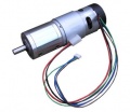
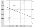
Ardumower gear motor with encoder (8mm diameter, 5900 rpm motor, 0.055 Nm, gear ratio 1/212, output torque 2.45Nm, output rpm 31)
Motor wiring
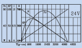
Ardumower gear motor curve (motor only)
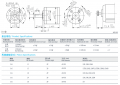
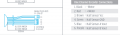
Gearbox specification


The two left and right gear motors are controlled independently (aka 'differential driving') to:
- drive the robot forward/backward
- steer the robot left/right
Wheel motor features:
- A rotation speed up to 31 rpm allows to move the robot at sufficient speed (at up to meter/sec = 31rpm/60 * PI * 0.25m = 0.4m/sec using 250mm diameter wheels)
- A high torque (2.45Nm) guarantees that the robot can climb small hills as well (with 2 motors, 0.125 radius wheel, 31rpm = 0.4m/s, acceleration = 0.2 ( 1/2 of nominal speed) see calculator
- Integrated encoders, so it can measure the rotation speed and the distance
- 24V (load current ~1A)
The left gear motor is connected as follows to the protector board:
Motor wiring (left motor):
Motor (black)  ==== Protector board Motor_1_OUT(1)
Motor (red)    ==== Protector board Motor_1_OUT(2)
For right motor, use Protector board Motor_2_OUT(1,2) accordingly.
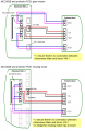
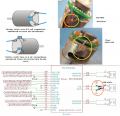
Wheel motors odometry wiring
The Ardumower gear motors have integrated encoders. These encoders help us to compute speed and traveled distance. Here's how you connect the motor odometry wires to the PCB.
Motor wiring
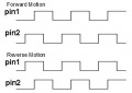
Encoder signal

Motor odometry wiring (left motor):
Motor (brown)  ---- PCB VCC
Motor (green)  ---- PCB GND
Motor (blue)   ---- PCB OdometryLeft (3)
Motor (purple) ---- PCB OdometryLeft (4)
For right motor, use PCB OdometryRight accordingly.
IMPORTANT: PCB v0.5/1.2 are missing pull-up resistors! You need to add them yourself at the PCB:
PCB OdometryLeft(3) --- 4.7k --- 5v
PCB OdometryLeft(4) --- 4.7k --- 5v
Mower motor wiring
PCB, MC33926, protector and motors
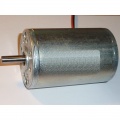
Ardumower mower motor
Ardumower mower motor curve
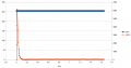
Mower start current
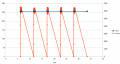
Mower blocked, 500ms detection (max), waittime: 5sec (min)


The Ardumower mower motor features:
- Fast enough to cut the lawn (3150 rpm)
- Enough torque (140 mNm / 46 W)
- Quiet mowing (you cannot hear it)
- 24V, load current ~1.0A (L=2.8mH, R=1.9ohm)
![]() Security note: For security reasons, always remove mower blades in your first tests!
Security note: For security reasons, always remove mower blades in your first tests!
Here's how you connect the mowing motor to the protector board:
Motor (black)  ==== Protector board Motor_1_OUT(1)
Motor (red)    ==== Protector board Motor_1_OUT(2)
Motor decrease noise
Here's how you can decrease motor noise:
Decrease motor noise

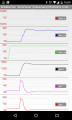
Motor controller (PID)
The speed of the motors is controlled by a software PID controller. You can monitor the quality of the motor speed control via pfodApp (Plot->Motor control):
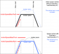
Motor speed settings