Perimeter wire: Unterschied zwischen den Versionen
(→Perimeter) |
(→Abstract) |
||
| Zeile 4: | Zeile 4: | ||
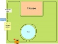
Principle idea: You will install a perimeter loop (a wire) in your garden through which a signal is sent and this signal is detected by the robot. So, you'll need: a sender (to transmit the on the wire) and a receiver (to detect the signal in the robot). | Principle idea: You will install a perimeter loop (a wire) in your garden through which a signal is sent and this signal is detected by the robot. So, you'll need: a sender (to transmit the on the wire) and a receiver (to detect the signal in the robot). | ||
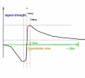
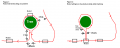
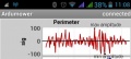
| − | How is the signal detected? The signal is detected by one | + | How is the signal detected? The signal is detected by one receiver coils. The closer the distance between coil and perimeter loop, the higher the signal strength. Also, something interesting happens when the robot crosses the perimeter loop: the signal changes its polarity, that means positive and negative voltages reverse each other. |
<gallery> | <gallery> | ||
Version vom 30. Mai 2016, 13:46 Uhr
Inhaltsverzeichnis
Abstract
A perimeter wire (or buried wire fence, BWF) is like a 'virtual fence': it stopps the robot when it reaches its boundaries. A perimeter is not always necessary for all surroundings.
Principle idea: You will install a perimeter loop (a wire) in your garden through which a signal is sent and this signal is detected by the robot. So, you'll need: a sender (to transmit the on the wire) and a receiver (to detect the signal in the robot).
How is the signal detected? The signal is detected by one receiver coils. The closer the distance between coil and perimeter loop, the higher the signal strength. Also, something interesting happens when the robot crosses the perimeter loop: the signal changes its polarity, that means positive and negative voltages reverse each other.
Perimeter wire
Components
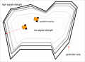
Signal strength
Perimeter gradient
Excluding objects
Dividing areas


Perimeter
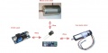
This is the new version of the perimeter sender and receiver (that can be purchased via the shop ![]() ).
).
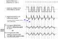
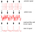
The perimeter sender outputs a digital code sequence (a 'pseudo-noise' code), and the receiver will detect that code using a software-based digital matched filter. Depending on wheter the match result peak is positive or negative, the robot is inside or outside of the perimeter wire.
Principle:
- Generate output signal by Arduino Nano (about 3 Khz)
- Amplify output signal by motor driver (MC33926), motor driver output connected to the perimeter wire (instead of a motor)
- Receive input signal with perimeter coil
- Amplify input signal with an operational amplifier (LM386)
- ADC sampling using Arduino Mega (at 9615 Hz)
- Signal filterung and signal detection using a digital filter (software-based matched filter algorithmn)
- Evaluation of matched filter output (for perimeter inside/ouside detection, tracking etc.)
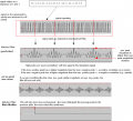
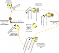
The images below explain why the polarity of the received coil signal changes between inside and outside of the perimeter wire. The image shows the direction of the electric flux lines sent out from the perimeter wire and how they hit the coil for both inside and outside position. For a better understanding of the perimeter filter, see the Matched filter simulation. For more details about the filter, also see the Matched filter video.
Inside/outside detection using polarity change
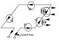
Flux directions
Perimeter signal at sender and receiver coil
Matched filter
What makes a good/bad signal


Sender
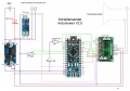
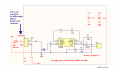
Sender circuit
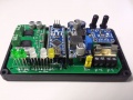
Ardumower sender PCB
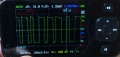
Sender signal (6.5V, open perimeter)
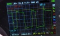
Sender signal (6.5V, 120m/7 Ohm closed perimeter)
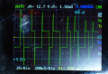
Sender signal (6.5V, 2m + 4ohm R, closed perimeter)
Perimeter wiring options


We use a motor driver as output amplifier and an Arduino Nano to generate the signal. The motor driver is driven by 3.2 Khz (two pulse widths 4808 Hz and 2404 Hz). With large enough perimeter wires, the circuit typically draws 10W (6.5V, 1.7A). We use a motor driver with integrated current limiting and thermal switch-off (e.g. MC33926). The perimeter wire length should be in the range 20m - 450m and must be at least 5 Ohm.
Example of sender implementation on a dot matrix board: [1] [2] [3]
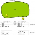
Sender perimeter lawn size
At an operating voltage of 6.5V, the perimeter wire length should not exceed 450m. For 'kitchen test' a 100 Ohm resistor in series with 5m wire could make the job!
Assuming an ideal lawn shape (circle shape), we get a lawn radius:
radius = length / (2*PI) = 450m / (2*PI) = 70 meter
Assuming there is no maximum perimeter radius for good signal quality, the maximum lawn area size (ideal circle shape) would be:
area = PI * (r*r) = PI * (70m * 70m) = 15000 m2
However, assuming there is a maximum perimeter radius for good signal quality of 18m, the maximum lawn area size (ideal circle shape) would be:
area = PI * (r*r) = PI * (18m * 18m) = 1000 m2
Sender current control
To change the power (current/voltage) of the sender, you have several options:
- DC/DC Voltage: The motor driver supply voltage can be changed (6.5-12V via the potentiometer on the DC converter). That's one way to do it and it's the recommended way. NOTE: The minimum voltage (Vin) for the MC33926 motor driver is 5v. If the voltage is lower, the motor driver shuts down sporadically (undervoltage detection-Arduino LED starts to flash).
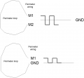
- Normal amplitude: Instead of switching the perimter wire between +Vin and -Vin (double amplitude/default), the motor driver can switch it between +Vin and GND (normal amplitude). This will reduce current. To use normal amplitude, comment out the corresponding code line in 'sender.ino':
// #define USE_DOUBLE_AMPLTIUDE 1
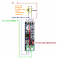
- Power resistor: If your perimeter wire resistance (R) is below 5 Ohms, you will not be able to further reduce voltage below 6.5v (otherwise the Arduino will not work properly). Then you have to increase the perimeter wire resistance (R) by using a power resistor (example: 5 ohm, 10W) in series with your perimeter wire.
@6 volts (Vin): 5 ohm power resistor => I=U/R=6v/5ohm=1.2A (P=U*I=6v*1.2A=7.2W)
So, your power resistor should be a 10W type or better. Activate 'normal-amplitude' in sender code (do not use double amplitude).
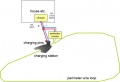
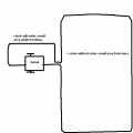
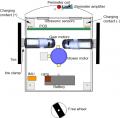
Sender automatic standby
The sender can be switched off during the time the robot is in the charging station. To detect the robot, a current sensor is connected between the charger and the charging pins.
Sender software
NOTE: If you have never worked with Arduino before or if your Arduino Nano does not seem to respond, please read our 'Arduino first steps' introduction.
Download: You can find the sender code in the 'sender' folder of the Ardumower Download
![]() Note: Always verify that the pin configuration in your Arduino code (sender.ino) matches your actual circuit!
Note: Always verify that the pin configuration in your Arduino code (sender.ino) matches your actual circuit!
In the sender.ino you have this option:
- Define if you have connected a charging current sensor for automatic sender standby: #define USE_CHG_CURRENT 1 (or 0)
Sender diagnostics
The perimeter sender status is indicated by the sender LED (Arduino Nano LED):
- ON: perimeter wire loop is closed and working
- OFF: perimeter wire loop is opened and not working
- blinking: robot is charging and perimeter will be switched OFF (energy saving)
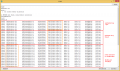
Perimeter sender console output

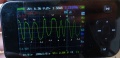
Test sender with your PC's sound card
You can use your sound card to try out the sender with just a coil:
- Connect a coil (100 mH) to your sound card microphone/line input (max 1V)
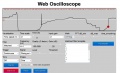
- Launch the web oscilloscope, and choose Filter 'Matched', Frequency '9615' Hz, Visualization Math 'MinMax'
- The output signal should reflect the distance to your perimeter loop - the polarity (negative/positive) should indicate the side of the loop (inside/outside)
Try to move the coil as close as possible to the perimeter loop (for both inside/outside case) (Keep in mind that this is without pre-amplifier, so the signal will be only valid close to the loop - the microphone input cannot be higher than 1V, so we cannot use the pre-amplifier here).
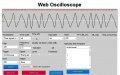
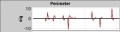
Actual received time signal (Filter Off, Time scale: x5)
Ideal time signal, generated by sender (Filter Off, Time scale: x5)
Matched filter signal (Frequency: 9615 Hz, Math: MinMax)
What makes a good/bad signal


Receiver
For receiving the signal, we use a coil (100 mH or 150 mH) in upright position (centered at front in robot) connected to an LM386 operational amplifier (to amplify the received signal). When using the LM386 module, capacitor C3 on the LM386 module should be bypassed (which is needed so that the LM386 generates a signal between 0..5V and not the default range -5V..+5V). The LM386 output pin should be connected to an analog Arduino pin ('pinPerimeterLeft').
Receiver circuit and shortened capacitor C3
Perimeter coil position
One centered, upright coil
LM386 module schematics
NOTE: Keep away coil/pre-amplifier from DC/DC converters
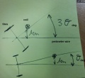
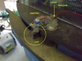
Tire-coil distance effecting rotation angle


You can get the receiver kit in the shop
NOTE: It's recommended to directly mount the coil on the amplifier module. This ensures the 'small signal' of the coil is not distorted by other components (motors, DC/DC converters etc.).
Note: Leave out capacitor 4.7nF in latest software versions ('using differential signal').
Settings
Perimeter settings

pfodApp->Options->Perimeter:
- Timed-out if below smag (timedOutIfBelowSmag) - default setting: 300 | If smag below this value, sender is considered as off (perimeter timeout appears)
- Timeout (s) if not inside (timeOutSecIfNotInside) - default setting: 8
- Trigger timeout (perimeterTriggerTimeout) - default setting: 0 | Perimeter outside trigger timeout when escaping from inside (ms)
- Perimeter out roll time max (perimeterOutRollTimeMax) - default setting: 2000 | Max (random generator) roll time after perimeter out (ms)
- Perimeter out roll time min (perimeterOutRollTimeMin) - default setting: 750 | Min (random generator) roll time after perimeter out (ms)
- Perimeter out reverse time (perimeterOutRevTime) - default setting: 2200 | Time to drive reverse after perimeter out (ms)
- Perimeter tracking roll time (perimeterTrackRollTime) - default setting: 1500 | Hit obstacle while tracking: roll time
- Perimeter tracking reverse time (perimeterTrackRevTime) - default setting: 2200 | Hit obstacle while tracking: reverse time
- Transition timeout (trackingPerimeterTransitionTimeOut) - default setting: 2000 | Max. time required for a in/out transition during tracking, robot will start rotating after this timeout
- Track error timeout (trackingErrorTimeOut) - default setting: 10000 | Max. time required for a in/out transition during tracking, robot will go into error after this time
- Track_P (perimeterPID.Kp) - default setting:51 | Perimeter PID "P" setting
- Track_I (perimeterPID.Ki) - default setting:12.5 | Perimeter PID "I" setting
- Track_D (perimeterPID.Kd) - default setting:0.8 | Perimeter PID "D" setting
- Use differential signal (useDifferentialPerimeterSignal) - default setting: YES | Use differential signal (see signal section)
- Swap coil polarity (swapCoilPolarity) - default setting:NO
- Block inner wheel (trackingBlockInnerWheelWhilePerimeterStruggling) - default setting: YES | robot is wheel-spinning while tracking => roll to get ground again
Coil/amplifier-to-motor distances
Ensure all minimum distances to the following components:
* Coil to gear motor: > 15cm
* Coil to mower motor: > 10cm
* Coil to DC/DC converter: > 10cm
NOTE: Keep away coil/pre-amplifier from DC/DC converters and motors!
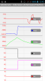
Signal measurements
The sender / coil / LM386 amplifier outputs should look like this: (for more details about the signal, see section signal above)
Perimeter signal at sender, receiver coil, and LM386 (theory)
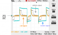
differential signal/coil signal without capacitor (5V sender, 5 ohm loop - blue: perimeter, yellow: coil, gray: LM386 amplifier out)
LM386 output, with DC noise (differential signal/coil without capacitor)
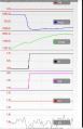
LM386 output (non-differential signal/coil with capacitor, 12V sender, 120m loop)
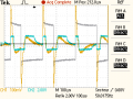
non-differential signal/coil signal with capacitor (5V sender, 5 ohm loop - gray: perimeter, yellow: coil, blue: LM386 amplifier out)

LM386 output, with motor noise (differential signal/coil without capacitor)


Receiver ADC calibration
![]() The ADC calibration ensures that the zero point (silence) is detected correctly, and so later the received signal is symmetric around zero.
The ADC calibration ensures that the zero point (silence) is detected correctly, and so later the received signal is symmetric around zero.
- The perimeter sender and robot motors must be switched off during calibration!
- If you cannot avoid that another sender is disturbing during calibration, remove the coil during calibration (connect LM386 input line to GND)
- Run the ADC calibration once ("pfodApp->ADC Calibration")
When calibrated correctly, the signal in the pfodApp plot ('sig') should be around zero (0) when the perimeter sender is switched off. When the perimeter sender is switched on, the plotted signal ('sig') should have the same maximum amplitude for both positive and negative axis (is 'symmetric around zero').
symmetric signal when sender is on (after ADC calibration)
zero signal when sender is off (after ADC calibration)

Receiver diagnostics/troubleshooting
The receiver signal, filter result and signal quality can be monitored via Android phone (pfodApp->Plot->Perimeter):
Signal-to-noise ratio (SNR)
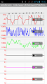
signal, filter result, LP filter result, inside/outside, counter, on/off, quality
Moving from inside to outside
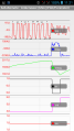


Plot signal description:
sig:  coil signal (raw pulse sequence after ADC) - it's a short snapshot (32 samples), and it's taken every 20 seconds
      (so you need to wait 20 seconds for the next snapshot)
mag:  filter result: inside (negative) or outside (positive), magnitude: distance to perimeter wire/magnetic signal strength (RSSI)
      - this is used for perimeter tracking
smag: filter result, low-pass filtered, without sign (smooth mag) - this is used for 'sender-off' detection
      The threshold can bet set via pfodApp (Settings->Perimeter->Timed-out if below smag)
in:   binary result, low-pass filtered: inside (1) oder outside (0) - this is used for perimeter boundary detection
      If the robot is not inisde for a certain time, it will go into error. The threshold can bet set via pfodApp
      (Settings->Perimeter->Timeout (s) if not inside)
cnt:  number of "inside-outside" transitions (counter)
on:   perimeter sender active, robot is inside and smag is high enough (1) or inactive/outside/smag too low (0)
qty:  signal quality (how distinguisable inside and outside were in filter result
      computes ratio:  match score with template signal / match score with inverse template signal
      1.0 means poor quality, you should get 1.5 or higher)
The 'mag' plot should be clear (without spikes): Inside the perimeter loop, the signal should be a clear negative curve, outside it should be a clear positive curve. If your 'mag' curve is not clear (and has spikes), try to troubleshoot/optimize:
- Always test using long, correctly rolled-off perimeter wire (20m or longer) - Never use unrolled or too short perimeter wire. For 'kitchen test' a 100 Ohm resistor in series with 5m wire @ 5V could make the job
- Verify, your coil is connected correctly at 'pinPerimeterLeft' (you still may get a poor signal when connected at a wrong Arduino pin!)
- Decrease the threshold for a smag timeout via 'pfodApp->Options->Perimeter->Timed-out if below smag'
- Reverse coil if the in/out is inverted or reverse the perimeter wire
- Minimize cable length between coil and LM386-pre-amplifier (directly mount coil onto pre-amplifier)
- Increase distance between coil and mower motor/DC converter (move away coil 30cm or more from any motors or DC converters)
- Add some magnetic shield (e.g. your battery) between coil and motors/DC converter
- Adjust voltage of sender: increase voltage (sender DC converter potentiometer) for for longer perimeter (>80m), decrease (sender potentiometer) for shorter perimeter (>25m)
- While motors are running, try to tilt coil slightly to one side so that 'qty' curve increases
Broken perimeter wire
Once in a while your perimeter wire may get broken, and your perimeter loop resistance will probably increase to a few Megaohms (MOhm). If that is the case, you can find the location of the break like this:
- Using a metal plate, plug one wire of the perimeter sender output into earth ground (the other wire of the sender output is still connected to the perimeter wire)
- Optional: increase your sender output voltage to 20 Volts (NOTE: the MC33926 driver can NOT operate higher than 28v, and your sender Arduino Nano may not operate higher than 20v)
- Method 1 (using two LM386 amplifiers and earphone): Connect 1st LM386 amplifier (NOTE: do NOT remove capacitor C3!) signal output to a 2nd LM386 input. Connect 2nd LM386 output to an earphone.
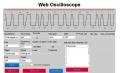
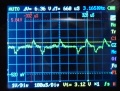
- Method 2 (using one LM386 amplifier and a PC): Connect the LM386 amplifier (NOTE: do NOT remove capacitor C3!) signal output (signal and GND) to your PC's microphone input, launch the web oscilloscope, and switch into frequency view (choose visualization 'frequency spectrum')
- Turn on the perimeter sender - while traversing the perimeter wire, you will notice a peak frequency of 3.2 Khz in the Web oscilloscope
- Now start at the side of the perimeter wire (the side that is still connected to the perimeter wire), and walk along the perimeter wire - the peak frequency of 3.2 Khz should always be there (and hearable)
- At the location where the wire is broken, the 3.2 Khz frequency is gone (and no longer hearable)! Demonstration video
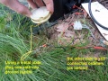
Plug one wire into ground (earth)
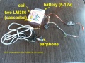
Method 1: Connect 1st LM386 amplifier output to 2nd LM386 input, 2nd output to earphone
Method 2: Connect LM386 amplifier output to your PC's microphone input
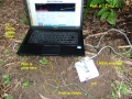
Method 2: Launch the web oscilloscope, and set frequency view


Measurements
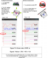
For your reference, here are some outdoor measurements of different sender/receiver/perimeter loop combinations:
1) 120m (0.7mm^2), R=4 Ohm, 6.5V, coil Vpp 20mV
Noise (max): smag=192
Signal (min): smag=254
SNR=Signal/Noise=254/192=1.3
2) 30m (0.7mm^2), R=1.0 Ohm (+4 Ohm series R), 6.5V, coil Vpp 120 mV
Noise (max): smag=192
Signal (min): smag=896
SNR=Signal/Noise=896/192=4.6
Videos
- Perimeter2 demo
- 120m perimeter wire test
- Perimeter wire and matched filter theory (German)
- Sender PCB
- Perimeter stop test
- Perimeter tracking test
- Finding and tracking test L50
- Finding and tracking test Rotenbach
- Magnetic field demonstration video
Tracking of perimeter
The tracking of the perimeter wire is performed using a (software) digital PID controller. The controller's parameters (P,I,D) can be configured via the phone (pfodApp).

![[2]](http://www.braunschweiger.org/content/images/SenderR212_Front.jpg)
![[3]](http://www.braunschweiger.org/content/images/SenderR212_Back.jpg)
You can find more information about PID controllers here: Forum.