DIY Brushless Driver Board: Unterschied zwischen den Versionen
BerndS (Diskussion | Beiträge) (→Prepare BL Driver Board and connect the cable) |
BerndS (Diskussion | Beiträge) (→Building the SPI Brushless Driver Programmer) |
||
| Zeile 16: | Zeile 16: | ||
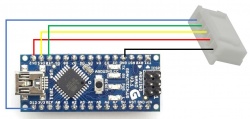
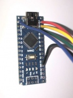
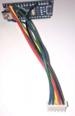
To build your own programmer for the controller DRV8308, you need an Arduino Nano and a 5 pin JST-XH plug with cramped wires. | To build your own programmer for the controller DRV8308, you need an Arduino Nano and a 5 pin JST-XH plug with cramped wires. | ||
Solder the wires as shown in the picture and ready is the programmer hardware. | Solder the wires as shown in the picture and ready is the programmer hardware. | ||
| − | Download the Nano program, you can finde here, and load it on the Arduino Nano. | + | Download the Nano program, you can finde here on github, and load it on the Arduino Nano. |
Let the Arduino Sketch programm open, we need it later. | Let the Arduino Sketch programm open, we need it later. | ||
Version vom 14. März 2021, 00:54 Uhr
Inhaltsverzeichnis
DIY ArduMower Brushless Driver Kit
In this chapter you will find the information about the DIY ArduMower Brushless Driver, based von TI DRV8308 Chip.
General Information about the ArduMower Brushless Driver like architecture and furth options, you will find in another WiKi [1]
Description
DIY ArduMower Brushless Driver, this is a not configured Driver, as it comes out of the factory. It is for experts, able to program there own configuration to the device. It is needed if you want to use another mower than an ArduMower with other types fo motors. For this, you need expert knowledge about electronics / brushless motors and software skill. With this kits, you are working on you own risk.
One IMORTANT notice at the beginning: The OTP ROM, where you have to store the program parameter for your motor, can programmed only ONE time! OTP-ROM changes afterwards are not possible. So please think twice before you burn the parameter into OTP-ROM. More on this later in this article.
Building the SPI Brushless Driver Programmer
Before you start the assembling of the Driver Board, we will build the programmer. To build your own programmer for the controller DRV8308, you need an Arduino Nano and a 5 pin JST-XH plug with cramped wires. Solder the wires as shown in the picture and ready is the programmer hardware. Download the Nano program, you can finde here on github, and load it on the Arduino Nano. Let the Arduino Sketch programm open, we need it later.
Connector Pinout
Build BL Driver Board and connect the cable
Step 1 Soldering :
Okay, you are an expert, you do not need an Instruction how to solder some parts on a PCB. Lets go to step 2
Step 2 Connect the Brushless Motor : Have a look into the motors datasheet and identify the motor coils U,V & W wires and connect them to the board connector. Also identify the HAL sensors for coil U,V & W and connect them to the HAL board connector as well.
Step 3 Connect the Power :
Also easy for you, connect the power cable, but switch the power off before! Please take care that you have the right polarity! The +24V power to the connector marked + and ground / - pole to the connector marked - . Check it twice! If you do it wrong, the 3.5A fuse on the board will blow up and you have to change it.
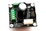
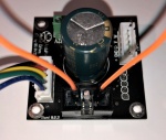
Finaly your board should look like in the picture.
Test the motor and adapt the parameter
All power is off for Driver Board and Arduimo Nano Programmer. You have connected the power, the motor coils, and the HAL sensors. Bridge the EN signal (pin2) and GND (pin 7) on the 8 pin flat cable connector and plug in the Nano SPI plug into the SPI Board connector.
Ok, now cablinbg is done. Please double check the right 24V polarity of the board power.
Please not, if your motor does not run with the preset parameters, it will caused in unexpected reactions of the motor, So, please take care that the motor is fix and secure on your table. Later, if we start the motor, have one finger on the power off button, to switch power of if the motor jammed.
If all connections are correct, you can power on the 24V power for the Driver Board. Don't panic is nothing happened, that's normal, because there are no parameter set in the driver.
Attention, the next step will start your motor! Be prepared to power off the 24V power if the motor jammed. Now you can plug in the USB connector into the Arduino Nano to power on your programmer. After 1-2 seconds the Motor will start turning. If he runs smooth you can take away your finger from the off button and go ahead with testing.
