Bumper-Sensor: Unterschied zwischen den Versionen
Aus www.wiki.ardumower.de
| Zeile 34: | Zeile 34: | ||
5 -- USB-TTL RX | 5 -- USB-TTL RX | ||
6 -- USB-TTL DTR (reset) | 6 -- USB-TTL DTR (reset) | ||
| + | |||
| + | =Verbinden mit Ardumower= | ||
| + | |||
| + | Set jumper to 'VIN', and connect VIN and BUMPER-OC to Ardumower as follows: | ||
| + | VIN | ||
| + | (+) -- 9-12V | ||
| + | (-) -- GND | ||
| + | |||
| + | BUMPER-OC | ||
| + | DC1 -- bumper1 output | ||
| + | DC2 -- bumper2 output | ||
=Videos= | =Videos= | ||
#[https://www.youtube.com/watch?v=IW93kSheB68 Introduction BumperDuino] | #[https://www.youtube.com/watch?v=IW93kSheB68 Introduction BumperDuino] | ||
#[https://www.youtube.com/watch?v=Crvdqs4AtvQ Making Of BumperDuino] | #[https://www.youtube.com/watch?v=Crvdqs4AtvQ Making Of BumperDuino] | ||
Version vom 15. Januar 2016, 00:44 Uhr
Inhaltsverzeichnis
Einführung
Ardumower's bumper sensor (called 'BumperDuino') is based on a pressure sensor and helps us to detect obstacles.
The PCB module and sensor can be purchased as complete kit via the shop ![]() .
.
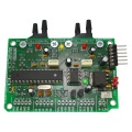
BumperDuino PCB
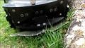
BumperDuino pressure sensor tube
BumperDuino pressure sensor tube
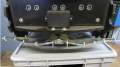
BumperDuino building instructions


Bauanleitung
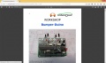
Building instructions can be found in the BumperDuino manual.
Schaltbilder
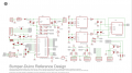
BumperDuino schematics

Code
You can download the Arduino Code here. Important: Choose 'Arduino Uno' as bootloader.
To upload the code, set jumper to 'VUSB' and connect an USB-TTL adapter to J4 (USB-LIGHT) as follows:
J4 (USB-LIGHT)
1 -- USB-TTL GND
2 -- not used
3 -- USB-TTL +5V
4 -- USB-TTL TX
5 -- USB-TTL RX
6 -- USB-TTL DTR (reset)
Verbinden mit Ardumower
Set jumper to 'VIN', and connect VIN and BUMPER-OC to Ardumower as follows:
VIN
(+) -- 9-12V
(-) -- GND

BUMPER-OC
DC1 -- bumper1 output
DC2 -- bumper2 output