Motor driver: Unterschied zwischen den Versionen
(→Mower motor and driver) |
(→Choosing a driver) |
||
| Zeile 77: | Zeile 77: | ||
[[File:warning.png]]'''Security note: For security reasons, always remove mower blades in your first tests!''' | [[File:warning.png]]'''Security note: For security reasons, always remove mower blades in your first tests!''' | ||
| − | |||
| − | |||
| − | |||
| − | |||
| − | |||
| − | |||
= Starting current = | = Starting current = | ||
Version vom 29. Mai 2016, 23:51 Uhr
Inhaltsverzeichnis
Abstract
Ardumower's design uses two different types of motors (all motors can be purchased via the shop ![]() ):
):
- Two motors (with integrated gearing) for driving (wheel motors), and encoder (for distance, direction and speed control)
- One motor (with high rotation speed) for mowing (mower motor)
To control a motor, it requires a 'motor driver'. Ardumower uses a dual MC33926 motor driver, so two channels for left and right motor.
Voltages
Although there exist 12V motors and 24V motors, as in all modern systems, the Ardumower uses 24V motors.
Wheel motors
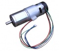
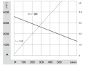
Ardumower gear motor with encoder (8mm diameter, 5900 rpm motor, 0.055 Nm, gear ratio 1/212, output torque 2.45Nm, output rpm 31)
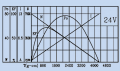
Ardumower gear motor curve (motor only)
Decrease motor noise

Motor encoder wiring


The two left and right gear motors are controlled independently (aka 'differential driving') to:
- drive the robot forward/backward
- steer the robot left/right
The Ardumower wheel motor features:
- A rotation speed up to 31 rpm allows to move the robot at sufficient speed (at up to meter/sec = 31rpm/60 * PI * 0.25m = 0.4m/sec using 250mm diameter wheels)
- A high torque (2.45Nm) guarantees that the robot can climb small hills as well (with 2 motors, 0.125 radius wheel, 31rpm = 0.4m/s, acceleration = 0.2 ( 1/2 of nomeinal speed) up to 14 degree) see calculator
- Integrated encoders, so it can measure the rotation speed, the distance and the direction (see Odometry for more information) - Encoders are REQUIRED for Ardumower software.
- 24V (load current ~1A)
Protector PCB
Protector board is adviced to be used between controller and motor.
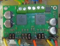
Motor driver (dual MC33926)
Features: up to 3A with integrated current sensor and thermal shut-down protection, for all kind of robot mowers)
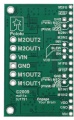
MC33926 pinout
MC33926 jumpers
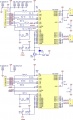
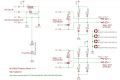
MC33926 schematics
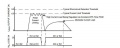
MC33926 automatic current limiter
Motor start 50% PWM transients
Peak/EMF protection


M1_FB     --- pinMotorLeftSense A1
M1_SF     --- pinMotorLeftFault 25
M1_PWM_D1 --- connect with jumper to GND
M1_PWM_D2 --- connect with jumper to VDD
M1_IN1    --- pinMotorLeftPWM 5
M1_IN2    --- pinMotorLeftDir 31
EN        --- pinMotorEnable  37
M2_FB     --- pinMotorRightSense A0
M2_SF     --- pinMotorRightFault 27
M2_PWM_D1 --- connect with jumper to GND
M2_PWM_D2 --- connect with jumper to VDD
M2_IN1    --- pinMotorRightPWM  3
M2_IN2    --- pinMotorRightDir 33
EN        --- pinMotorEnable  37
VDD       --- Arduino 5V
Mower motor
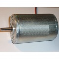
Ardumower mower motor
Ardumower mower motor curve
Mower start current
Mower blocked, 500ms detection (max), waittime: 5sec (min)


The Ardumower mower motor features:
- Fast enough to cut the lawn (3150 rpm)
- Enough torque (140 mNm / 46 W)
- Quiet mowing (you cannot hear it)
- 24V, load current ~1.0A (L=2.8mH, R=1.9ohm)
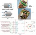
For a the mowing motor, a MOSFET circuit is used. The MOSFET transistor IRLIZ44N (alternatives: IRF1404, IRL540N, RFP30N06LE, FQP30N06L) can already switch a current of 30A at the Arduino 5V control signal (N-LogL). The 10K resistor pulls down to ground when the Arduino starts. The 180 Ohm resistor limits the current at the Gate caused by level switches to about 30mA. The diode (MBR1045) protects the circuit against current caused by motor induction. A current sensor module (ACS712-30A) is connected in series with the motor.
![]() Security note: For security reasons, always remove mower blades in your first tests!
Security note: For security reasons, always remove mower blades in your first tests!
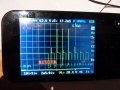
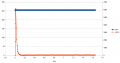
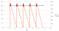
Starting current
Here are some measurements of the Ardumower motor's starting current (peak):
Starting current:
- Gear motor: 15A (starting current peak)
- Mowing motor: 20A (starting current peak)
Gear motor start current (peak)

Short-circuit current
To not damage the motor driver on the first run, find out the maximum current that can flow through your motors. In other words, find out the 'short-circuit' current. Typical measurement installation:
Battery === Ampere meter === Motor
The Amperemeter (e.g. model making) should be able to measure the maximum current (e.g. 30A). The motor to be measured is mechanically blocked (so it cannot rotate).
Warning
- always remove blades
- only connect battery for a short period (1-5 seconds)
- always use cables with sufficient wire cross section
Example measurement:
- Rotenbach SPM08-320
- Wheel motor: 8A
- Mowing motor:
- Ambrogio L50
- Wheel motor: 4,5A
- Mowing motor: 22A
- Tianchen TC-G158
- Wheel motor: 5,4A
- Mowing motor: 16A (both 32A)
The measured current will only flow in 'worst-case' scenarios, which means when the motor starts or when it is blocked and it will only flow for a short time (as your battery might not deliver the high current constantly, and so current and voltage will break down).
Current sensor
To detect certain conditions (robot drives against obstacle, motor blocks etc.), the motor current should be monitored constantly. There are two approaches for sensing current.
Approach "Hall sensor module"
This is the recommended approach for sensing current. These current sensor modules are available for different current ranges.
- ACS712ELC-05A (185mV/A, max. 5A)
- ACS712ELC-20A (100mV/A, max. 20A)
- ACS712ELC-30A (66mV/A, max. 30A)
- The lower the range, the more precise the measurement.
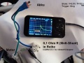
Approach "Shunt resistor (circuit)"
The current flows across a very small resistor (0.5 Ohm) and the voltage drop is measured

Further links
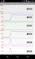
Motor controller (PID)
The speed of the motors is controlled by a software PID controller. You can monitor the quality of the motor speed control via pfodApp (Plot->Motor control):
Motor speed settings


Programming
Motor variables
// --------- wheel motor state ----------------------------
// wheel motor speed ( <0 backward, >0 forward); range -motorSpeedMaxRpm..motorSpeedMaxRpm
// [Default value]
float motorAccel ; // motor wheel acceleration - only functional when odometry is not in use
// (warning: do not set too high) [1000]
int motorSpeedMaxRpm ; // motor wheel max RPM [25]
int motorSpeedMaxPwm ; // motor wheel max Pwm (8-bit PWM=255, 10-bit PWM=1023) [255]
float motorPowerMax ; // motor wheel max power (Watt)
PID motorLeftPID; // motor left wheel PID controller [Kp=1.5 , Kd=0.29, Ki=0.25]
PID motorRightPID; // motor right wheel PID controller
float motorSenseRightScale ; // motor right sense scale (mA=(ADC-zero)/scale)
float motorSenseLeftScale ; // motor left sense scale (mA=(ADC-zero)/scale)
int motorRollTimeMax ; // max. roll time (ms)
int motorRollTimeMin ; // min. roll time (ms)
int motorReverseTime ; // max. reverse time (ms)
long motorForwTimeMax; // max. forward time (ms) / timeout
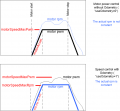
float motorBiDirSpeedRatio1 ;// bidir mow pattern speed ratio 1
float motorBiDirSpeedRatio2 ;// bidir mow pattern speed ratio 2
bool motorRightSwapDir ; // inverse right motor direction?
bool motorLeftSwapDir ; // inverse left motor direction?
int motorLeftSpeedRpmSet ; // set speed
int motorRightSpeedRpmSet ;
float motorLeftPWMCurr ; // current speed
float motorRightPWMCurr ;
int motorRightSenseADC ;
int motorLeftSenseADC ;
float motorLeftSenseCurrent ;
float motorRightSenseCurrent ;
float motorLeftSense ; // motor power (range 0..MAX_MOTOR_POWER)
float motorRightSense ;
int motorPowerIgnoreTime;
int motorZeroSettleTime; // how long (ms) to wait for motor to settle at zero speed
int motorLeftSenseCounter ; // motor current counter
int motorRightSenseCounter ;
unsigned long nextTimeMotorSense ;
unsigned long lastSetMotorSpeedTime;
unsigned long motorLeftZeroTimeout;
unsigned long motorRightZeroTimeout;
boolean rotateLeft;
unsigned long nextTimeRotationChange;
Motor Methods
First the basic function that control the pwm to each motors:
void setMotorPWM(int pwmLeft, int pwmRight, boolean useAccel);
A general methods to test motors
void testMotors();
Then, there are several MotorControl methods according to mower state :
if current state is 'STATE_PERI_TRACK' then
void motorControlPerimeter();
void motorControlImuRoll();
void motorControlImuDir();
for all other case :
 void motorControl();
 // This method calculate pwm to set in order to respect rpm setpoint according current rpm and Kp, Ki, Kd parameter