PCB 1.2 (English): Unterschied zwischen den Versionen
(→PCB modules) |
|||
| (34 dazwischenliegende Versionen desselben Benutzers werden nicht angezeigt) | |||
| Zeile 2: | Zeile 2: | ||
[[File: Pcb_top.jpg | 800px]] | [[File: Pcb_top.jpg | 800px]] | ||
| − | This page describes how to assemble the Ardumower PCB, | + | This page describes how to assemble the Ardumower PCB and how to add the modules. |
| + | |||
| + | ===Required parts for the Ardumower=== | ||
| + | [[Image:Ardumower_overview.png|thumb|700px|Overview]] | ||
| + | |||
| + | All modules can be purchased as complete kits via the [https://www.marotronics.de/index.php?k=7 shop] [[File: shopping.png|link=https://www.marotronics.de/index.php?k=7]] . | ||
| + | |||
| + | What is needed for building your Ardumower: | ||
| + | *[https://www.marotronics.de/Ardumower-Board-12-Prototyp-mit-Chassis-und-Motoren The Ardumower chassis including motors] | ||
| + | *Important modules to choose: | ||
| + | **[https://www.marotronics.de/Zubehoer-Set-fuer-das-Ardumower-Board-24-V Accessories Set (resistors, pin strips etc.)] | ||
| + | **[https://www.marotronics.de/Protector-Board-zum-Schutz-der-Motortreiber-vor-hohen-Induktionsspannungen 2 x Motor driver protection PCB] | ||
| + | **[https://www.marotronics.de/Mega-Board-2560-R3-ATmega2560-mit-USB-Kabel-Arduino-kompatibel-mit-CH340G-IC 1 x Mega Board 2560 R3] | ||
| + | **[https://www.marotronics.de/INA169-Analog-DC-Current-Sensor-Breakout-60V-25A-/-5A-Marotronics 1 x INA169 Current Sensor Board] | ||
| + | **[https://www.marotronics.de/Dual-MC33926-Motor-Driver-Carrier 2 x Dual motor driver MC33926] | ||
| + | **[https://www.marotronics.de/DC-DC-Spannungsregler-LM2596-Step-Down-Regler-einstellbar 2 x DC-DC LM2596 Step-Down Converter] | ||
| + | **[https://www.marotronics.de/HC-05-Wireless-Bluetooth-RF-Transceiver-Module-Serial-RS232-fuer-Arduino 1 x Wireless Bluetooth module HC-05] | ||
| + | **[https://www.marotronics.de/Real-Time-Clock-Modul-I2C-RTC-DS1307-zB-fuer-Arduino 1 x Real Time Clock I2C DS1307] | ||
| + | **[https://www.marotronics.de/Ladegeraete-fuer-den-Ardumower-Akkus-24V-mit-Status-LED-auch-fuer-Li-Ion-Akkus 1 x 24 Volt Charger for the Ardumower LithiumIon Battery] | ||
| + | |||
| + | *Optional modules: | ||
| + | **[https://www.marotronics.de/Bumper-Duino-Dual-Drucksensor-Board-zB-fuer-Arduino-Raspberry-pi BumperDuino (intelligent bumper sensor)] | ||
| + | **[https://www.marotronics.de/Perimeter-Sender-Board-Prototyp-mit-Platinen-Zubehoer Perimeter sender] and [https://www.marotronics.de/Schleifenempfaenger-Kit-perimeter-receiver-Kit receiver] | ||
| + | **[https://www.marotronics.de/Zubehoer-Set-fuer-die-Laderegelung-Blei-Batterien Charger Accessories Set (Lead Battery)] | ||
| + | **[https://www.marotronics.de/HC-SR04-Ultraschallsensor-Ultrasonic-Ranging-Module Ultrasonic sensor HC-SR04 (up to 3 supported)] | ||
| + | **[https://www.marotronics.de/Regensensor-Modul-YL-38-fuer-Arduino-Raspberry-PI-Regentropfen-Sensor-Naessesensor Rain sensor] | ||
| + | **[https://www.marotronics.de/9-Achsen-IMU-Sensor-GY-801-L3G4200D-ADXL345-HMC5883L-BMP180 IMU GY-80] | ||
| + | **[https://www.marotronics.de/Unterspannungsschutz-Board-Undervoltage-lockout-board Undervoltage protection PCB] | ||
| + | **[https://www.marotronics.de/NEO-6M-GPS-Modul-GY-GPS6MV2-NEO-6M-Flight-Controller-zb-fuer-Arduino GPS Module GY-GPS6MV2] | ||
| + | **[https://www.marotronics.de/ESP8266-WIFI-Wlan-Serial-Modul-ESP01-fuer-Arduino WIFI/Wlan Module ESP8266 ESP01] | ||
| + | *1 x [http://www.asn-shop.de/Ardumower-Power-Pack-259V-45Ah Ardumower Power Pack] | ||
| + | *1 x [https://www.marotronics.de/3-Messer-3-Schrauben-passend-zB-fuer-AutomowerZ-von-HusqvarnaZ 3 mowing blades + 3 screws, e.g. suitable for Automower® from Husqvarna®] | ||
=Abstract= | =Abstract= | ||
| Zeile 30: | Zeile 61: | ||
* Max. trace current (for motors): 8A | * Max. trace current (for motors): 8A | ||
| − | ==PCB building manual== | + | ===PCB building manual=== |
Robot PCB v0.5 (initial prototype, please do not use anymore) | Robot PCB v0.5 (initial prototype, please do not use anymore) | ||
* [https://github.com/Ardumower/ardumower/tree/master/pcb/Produzierte_Platinen/megashield_svn_0.5/Platinenbilder Photos] | * [https://github.com/Ardumower/ardumower/tree/master/pcb/Produzierte_Platinen/megashield_svn_0.5/Platinenbilder Photos] | ||
| Zeile 49: | Zeile 80: | ||
'''NOTE:''' The schematics and PCB files were created with KiCad. They can be downloaded from [https://github.com/Ardumower/ardumower/archive/master.zip github] and can be edited by open source KiCAD software (Download [https://docs.google.com/uc?id=0BzTsqkQk2FRsSEhOR2tVc1p4LVk&export=download here] or [http://iut-tice.ujf-grenoble.fr/cao/KiCad_stable-2013.07.07-BZR4022_Win_full_version.exe here]). | '''NOTE:''' The schematics and PCB files were created with KiCad. They can be downloaded from [https://github.com/Ardumower/ardumower/archive/master.zip github] and can be edited by open source KiCAD software (Download [https://docs.google.com/uc?id=0BzTsqkQk2FRsSEhOR2tVc1p4LVk&export=download here] or [http://iut-tice.ujf-grenoble.fr/cao/KiCad_stable-2013.07.07-BZR4022_Win_full_version.exe here]). | ||
| − | ==PCB building videos== | + | ===PCB building videos=== |
* [https://www.youtube.com/watch?feature=player_embedded&v=smZj60sxQvU Resistors] | * [https://www.youtube.com/watch?feature=player_embedded&v=smZj60sxQvU Resistors] | ||
* [https://www.youtube.com/watch?feature=player_embedded&v=chEBCcJDsjg Diodes and relay] | * [https://www.youtube.com/watch?feature=player_embedded&v=chEBCcJDsjg Diodes and relay] | ||
| Zeile 61: | Zeile 92: | ||
* [https://www.youtube.com/watch?feature=player_embedded&v=M-rC03VlGK4 Battery & charger] | * [https://www.youtube.com/watch?feature=player_embedded&v=M-rC03VlGK4 Battery & charger] | ||
| − | ==PCB jumpers== | + | ===PCB jumpers=== |
{| class="wikitable" | {| class="wikitable" | ||
| Zeile 134: | Zeile 165: | ||
|} | |} | ||
| − | ==PCB modules== | + | ===PCB modules=== |
| − | + | ||
| − | + | ||
{| class="wikitable" | {| class="wikitable" | ||
| Zeile 214: | Zeile 243: | ||
|} | |} | ||
| − | ==PCB connectors== | + | ===PCB connectors=== |
{| class="wikitable" | {| class="wikitable" | ||
| Zeile 520: | Zeile 549: | ||
[[File:Ardumower_motordriver_overview.png|800px]] | [[File:Ardumower_motordriver_overview.png|800px]] | ||
| − | = Voltages = | + | === Voltages === |
As in all modern systems, Ardumower uses 24V motors. | As in all modern systems, Ardumower uses 24V motors. | ||
| − | = Motor driver assembly (dual MC33926) = | + | === Motor driver assembly (dual MC33926) === |
Motor driver features: up to 3A with integrated current sensor and thermal shut-down protection | Motor driver features: up to 3A with integrated current sensor and thermal shut-down protection | ||
| Zeile 537: | Zeile 566: | ||
For wiring of motor drivers, protector and motors, please open manual in section Protector PCB. | For wiring of motor drivers, protector and motors, please open manual in section Protector PCB. | ||
| − | =Protector PCB= | + | ===Protector PCB=== |
[[File:warning.png]] When quickly tunring motors from forward to backward (or vice versa), high voltage spikes appear. These high voltage spikes could damage the motor driver in the long run. To eliminate high voltage spikes, it is adviced to use a [https://github.com/Ardumower/ardumower/blob/master/Dokumentation/Protector%20Board/WORKSHOP%20Protector-Board.pdf Protector board] between motor driver and motor. Two Protector PCBs are required, one for the gear motors, and one for the mowing motor. | [[File:warning.png]] When quickly tunring motors from forward to backward (or vice versa), high voltage spikes appear. These high voltage spikes could damage the motor driver in the long run. To eliminate high voltage spikes, it is adviced to use a [https://github.com/Ardumower/ardumower/blob/master/Dokumentation/Protector%20Board/WORKSHOP%20Protector-Board.pdf Protector board] between motor driver and motor. Two Protector PCBs are required, one for the gear motors, and one for the mowing motor. | ||
| Zeile 549: | Zeile 578: | ||
* [https://github.com/Ardumower/ardumower/blob/master/Dokumentation/Protector%20Board/WORKSHOP%20Protector-Board.pdf Assembly manual: Protector board (required for safe-use of motor drivers!)] | * [https://github.com/Ardumower/ardumower/blob/master/Dokumentation/Protector%20Board/WORKSHOP%20Protector-Board.pdf Assembly manual: Protector board (required for safe-use of motor drivers!)] | ||
| − | = Wheel motors wiring = | + | === Wheel motors wiring === |
<gallery> | <gallery> | ||
File: Ardumower_motordriver_overview.png | PCB, MC33926, protector and motors | File: Ardumower_motordriver_overview.png | PCB, MC33926, protector and motors | ||
| Zeile 576: | Zeile 605: | ||
For right motor, use Protector board Motor_2_OUT(1,2) accordingly. | For right motor, use Protector board Motor_2_OUT(1,2) accordingly. | ||
| − | = Wheel motors odometry wiring = | + | === Wheel motors odometry wiring === |
The Ardumower gear motors have integrated encoders. These encoders help us to compute speed and traveled distance. Here's how you connect the motor odometry wires to the PCB. | The Ardumower gear motors have integrated encoders. These encoders help us to compute speed and traveled distance. Here's how you connect the motor odometry wires to the PCB. | ||
| Zeile 598: | Zeile 627: | ||
PCB OdometryLeft(4) --- 4.7k --- 5v | PCB OdometryLeft(4) --- 4.7k --- 5v | ||
| − | = Mower motor wiring = | + | === Mower motor wiring === |
<gallery> | <gallery> | ||
File: Ardumower_motordriver_overview.png | PCB, MC33926, protector and motors | File: Ardumower_motordriver_overview.png | PCB, MC33926, protector and motors | ||
| Zeile 619: | Zeile 648: | ||
Motor (red) ==== Protector board Motor_1_OUT(2) | Motor (red) ==== Protector board Motor_1_OUT(2) | ||
| − | = Motor decrease noise = | + | === Motor decrease noise === |
Here's how you can decrease motor noise: | Here's how you can decrease motor noise: | ||
| Zeile 630: | Zeile 659: | ||
* [http://www.ardumower.de/media/kunena/attachments/1725/Motor-EntstoerungREV20150531.pdf (English comments)] | * [http://www.ardumower.de/media/kunena/attachments/1725/Motor-EntstoerungREV20150531.pdf (English comments)] | ||
| − | |||
| − | |||
| − | |||
| − | |||
| − | |||
| − | |||
| − | |||
| − | |||
| − | |||
| − | |||
| − | |||
| − | |||
| − | |||
=Charger= | =Charger= | ||
| Zeile 654: | Zeile 670: | ||
If you are using an existing charger, these things are implemented with high probability already in it. If you don't want to use a charging station, the charger can be connected directly to the Ardumower. | If you are using an existing charger, these things are implemented with high probability already in it. If you don't want to use a charging station, the charger can be connected directly to the Ardumower. | ||
| − | =Total power balance= | + | ===Total power balance=== |
* 2 x Gear motors each 1A (under heavy load): 2A, 27 volt (measured at max. 80% accuracy by motor drivers) | * 2 x Gear motors each 1A (under heavy load): 2A, 27 volt (measured at max. 80% accuracy by motor drivers) | ||
* 1 x Mower motor 1A (under normal load): 1A, 27 volt (measured at max. 80% accuracy by motor drivers) | * 1 x Mower motor 1A (under normal load): 1A, 27 volt (measured at max. 80% accuracy by motor drivers) | ||
| Zeile 662: | Zeile 678: | ||
Total: 3A * 27v + 1A * 5v = 81W + 5W = 86W | Total: 3A * 27v + 1A * 5v = 81W + 5W = 86W | ||
| − | =Battery= | + | ===Battery=== |
[[File: Ardumower_battery_pack.jpg | Sony Konion 7S2P battery pack (29.4V, 4500 mAh)|400px]] | [[File: Ardumower_battery_pack.jpg | Sony Konion 7S2P battery pack (29.4V, 4500 mAh)|400px]] | ||
| Zeile 675: | Zeile 691: | ||
* discharging per cell: min 3.1v | * discharging per cell: min 3.1v | ||
| − | =Standby-off / Under-voltage protection= | + | Here you can see the charging without charging station. If you don't want to use a charging station (or for your first tests), the charger can be connected directly to the Ardumower: |
| + | |||
| + | [[File: Ardumower_battery_overview.jpg|800px]] | ||
| + | |||
| + | ===Standby-off / Under-voltage protection=== | ||
You can add an undervoltage protection to your Ardumower. There are two reasons for a battery switch (standby-off mechanism): | You can add an undervoltage protection to your Ardumower. There are two reasons for a battery switch (standby-off mechanism): | ||
| Zeile 689: | Zeile 709: | ||
[https://github.com/Ardumower/ardumower/tree/master/pcb/Produzierte_Platinen/Unterspannungsabschaltung_V1.0_geschlossen schematics] | [https://github.com/Ardumower/ardumower/tree/master/pcb/Produzierte_Platinen/Unterspannungsabschaltung_V1.0_geschlossen schematics] | ||
| − | = | + | ===Videos=== |
| + | #[http://www.youtube.com/watch?v=02REEUf99hI Driving into charging station] | ||
| + | #[http://www.youtube.com/watch?v=kfY6bBFdxYk Drive in and out] | ||
| + | #[https://www.youtube.com/watch?v=NLv-mXDqVQU&feature=youtu.be Tracking and docking] | ||
| + | #[https://www.youtube.com/watch?v=QCA6Dm3rs3M Final version] | ||
| + | |||
| + | =Bluetooth module= | ||
| + | On the robot, you'll need a Bluetooth HC-05 module supporting Bluetooth Serial Port Profile (SPP). SPP uses Bluetooth Service Discovery Protocol (SDP) and the RFCOMM protocol. | ||
| − | + | ===Bluetooth HC-05=== | |
| − | |||
<gallery> | <gallery> | ||
| − | File: | + | File: Pcb_bluetooth.jpg | PCB and HC-05 module |
| − | File: | + | File: Bluetooth_module.jpg | HC-05 module |
| − | File: | + | File: HC-05 schematics.jpg | HC-05 schematics |
| − | + | ||
</gallery> | </gallery> | ||
| − | + | Wiring: | |
| − | + | Bluetooth HC05 VCC --- PCB VCC | |
| + | Bluetooth HC05 GND --- PCB GND | ||
| + | Bluetooth HC05 TX --- PCB RX | ||
| + | Bluetooth HC05 RX --- PCB TX | ||
| − | + | For Programming the Module, you must connect the Key Pin from the BT Module to the 3.3 V from the PCB and disconnect after programming. | |
| − | + | = Ultrasonic Sensor = | |
| − | + | ||
| − | + | ||
| − | + | ||
| − | + | ||
| − | + | ||
| − | + | ||
| − | + | ||
| − | + | ||
| − | + | ||
| − | + | ||
| − | + | ||
| − | + | ||
| − | + | ||
| − | + | ||
[[File: ultrasonic.jpg | 400px]] | [[File: ultrasonic.jpg | 400px]] | ||
| Zeile 735: | Zeile 749: | ||
</gallery> | </gallery> | ||
| − | == Wiring == | + | === Wiring === |
Ultrasonic Module VCC (+5V) — PCB VCC (+5V) | Ultrasonic Module VCC (+5V) — PCB VCC (+5V) | ||
| Zeile 741: | Zeile 755: | ||
Ultrasonic Module Trigger — PCB Digital Pin | Ultrasonic Module Trigger — PCB Digital Pin | ||
Ultrasonic Module Echo — PCB Digital Pin | Ultrasonic Module Echo — PCB Digital Pin | ||
| − | |||
An internal schematics of the sensor can be found here.[http://uglyduck.ath.cx/ep/archive/2014/01/Making_a_better_HC_SR04_Echo_Locator.html] | An internal schematics of the sensor can be found here.[http://uglyduck.ath.cx/ep/archive/2014/01/Making_a_better_HC_SR04_Echo_Locator.html] | ||
| + | |||
| + | =Rain sensor= | ||
| + | |||
| + | Using a rain sensor, your Ardumower can stop mowing when it starts to rain. Additionally, it can drive into your charging station. | ||
| + | |||
| + | '''NOTE:''' If using YL-83 module, we have no long-term experience regarding corrosion! | ||
| + | |||
| + | <gallery> | ||
| + | File: Rain_sensor.jpg | Rain sensor module YL-83 | ||
| + | File: Rain_sensor.png | YL-83 schematics | ||
| + | File: PrinzipschaltungRegensensor.jpg | DIY rain sensor | ||
| + | </gallery> | ||
| + | |||
| + | ===Wiring=== | ||
| + | |||
| + | <blockquote style="background-color: lightgrey; border: solid thin grey;"> | ||
| + | <pre> | ||
| + | GND o-----o GND Rain sensor module | ||
| + | +5V o-----o VCC Rain sensor module | ||
| + | Ardumower pinRain o-----o D0 Rain sensor module | ||
| + | Rain sensor module IN o----- rain sensor | ||
| + | Rain sensor module IN o----- rain sensor | ||
| + | </pre> | ||
| + | </blockquote> | ||
| + | |||
| + | ===Photos=== | ||
| + | |||
| + | <gallery> | ||
| + | File: Ardumower_survival2.jpg | ||
| + | File: Ardumower_rain_sensor_example.jpg | ||
| + | </gallery> | ||
| + | |||
| + | ===Videos=== | ||
| + | #[https://www.youtube.com/watch?v=lLia2AjYHgc Rain sensor test] | ||
| + | #[https://www.youtube.com/watch?v=5Jwp4nEOTvM Simulated rain] | ||
| + | |||
| + | ===Further links=== | ||
| + | #[http://www.ardumower.de/media/kunena/attachments/1410/PrinzipschaltungRegensensor.jpg Principle schematics] | ||
| + | #[http://www.ardumower.de/index.php/de/forum/eure-ardumower-umsetzung/334-hasis-s-rasbot#4294 Rain sensor example] | ||
| + | |||
| + | =GPS= | ||
| + | <gallery> | ||
| + | File: ublox_neo_6m.jpg | ||
| + | |||
| + | File: GY-NEO6MV2_schematics.jpg | ||
| + | </gallery> | ||
| + | |||
| + | With the help of a GPS receiver (e.g. GY-NEO6MV2, ublox 6m), the long-term position can be calculated. Therefore, the GPS position values will be averaged. | ||
| + | |||
| + | Currently, GPS is used | ||
| + | * to receive current date and time | ||
| + | |||
| + | === Wiring: === | ||
| + | GPS VCC -- PCB VCC | ||
| + | GPS GND -- PCB GND | ||
| + | GPS TX -- PCB GPS RX | ||
| + | GPS RX -- PCB GPS TX | ||
| + | |||
| + | =Model R/C= | ||
| + | The Ardumower can be controlled via a model R/C. For remote controlling your robot mower you'll need: | ||
| + | |||
| + | *a model remote control (e.g. 2.4 Ghz) | ||
| + | *a suitable model remote receiver (4 channels or more) | ||
| + | |||
| + | <gallery> | ||
| + | File: Ardumower_rc.jpg | ||
| + | File: Ardumower_remote.jpg | ||
| + | </gallery> | ||
| + | |||
| + | ===Wiring=== | ||
| + | The channel assignment is: | ||
| + | |||
| + | <blockquote style="background-color: lightgrey; border: solid thin grey;"> | ||
| + | <pre> | ||
| + | left stick (left/right): pinRemoteSwitch | ||
| + | left stick (up/down): pinRemoteMow | ||
| + | right stick (left/right): pinRemoteSteer | ||
| + | right stick (up/down): pinRemoteSpeed | ||
| + | </pre> | ||
| + | </blockquote> | ||
| + | |||
| + | ===Videos=== | ||
| + | #[http://www.youtube.com/watch?v=C4OLHhklZto&feature=player_embedded demo] | ||
| + | |||
| + | |||
| + | =WIFI= | ||
| + | <gallery> | ||
| + | File: Esp8266.jpg | ||
| + | </gallery> | ||
| + | |||
| + | This is an advanced topic - only use a WIFI module if your Ardumower is fully working. A WIFI module can be used as an alternative for Bluetooth communication. Again, pfodApp is required to connect WIFI and the phone. | ||
| + | |||
| + | https://github.com/FredericG-BE/ardumower/wiki/Using-ESP8266-WIFI-module-on-Ardumower | ||
| + | |||
| + | = Realtime clock (RTC) = | ||
| + | The robot requires a clock, so that it can start mowing automatically at certain time intervals (timer). | ||
| + | |||
| + | A realtime clock (RTC) returns current time (minute, hour) and date (day of week, day, month, year) - by the help of a battery (Lithium Ion LIR2032, 3.6v, 48 mAh) the time continues to run even if the robot mower is switched off. | ||
| + | |||
| + | Additionally, the RTC module contains an EEPROM memory (non volatile memory) that can hold 4K of permanent user data. | ||
| + | |||
| + | DS1307 module | ||
| + | |||
| + | <gallery> | ||
| + | File: ds1307.jpg | ds1307 | ||
| + | |||
| + | File: ds1307_schematics.jpg | ds1307_schematics | ||
| + | </gallery> | ||
| + | |||
| + | === Troubleshooting "Tiny RTC I2C module" === | ||
| + | If your module is losing time/date, fix the circuit like this: | ||
| + | |||
| + | * Remove D1, R6 and R4 | ||
| + | * Solder jumper wire in place of R6 | ||
| + | * Inspect crystal soldering - fix if necessary | ||
| + | * Replace battery | ||
| + | |||
| + | === Wiring === | ||
| + | |||
| + | The RTC module is connected on the I2C bus of the Arduino Mega (in parallel with any other I2C modules). | ||
| + | |||
| + | <blockquote style="background-color: lightgrey; border: solid thin grey;"> | ||
| + | <pre> | ||
| + | DS1307 Module SDA — Arduino SDA Pin | ||
| + | DS1307 Module SCL — Arduino SCL Pin | ||
| + | DS1307 Module VCC (+5V) — Arduino VCC (+5V) | ||
| + | DS1307 Module GND — Arduino GND | ||
| + | </pre> | ||
| + | </blockquote> | ||
| + | |||
| + | === Note === | ||
| + | If you experience communication problems when using multiple I2C modules on one I2C bus, | ||
| + | it is recommended to reduce the length of the cables. | ||
| + | |||
| + | |||
| + | = Arduino Dropsensor - Absturzsensor = | ||
| + | |||
| + | '''Funktion:''' | ||
| + | |||
| + | Der Arduino Dropsensor oder auch Absturzsensor ist dafür gedacht den Mover vor abstürzen vor Treppenabsätzen oder ähnlichen zu schützen. Ebenso kann dieser eingesetzt werden um Inseln von Bäumen und Blumenbeeten zu erkennen. | ||
| + | Voraussetzung dafür ist allerdings das dieser an der Graskante hin zur Insel mit einem kleinen Graben umgeben wird damit dieser zuverlässig erkannt werden | ||
| + | |||
| + | '''Anschluß:''' | ||
| + | |||
| + | Benötigt werden 2 IR Entfernungssensoren. Am besten sind solche geeignet die bereits in einem externen Gehäuse eingebaut sind. Diese haben auch auf der Rückseite eine Einstellmöglichkeit für die Entfernung bzw Empfindlichkeit. Die Standard Ausführung benötigt 3 Anschlussleitungen . | ||
| + | +5V, GND, Signalleitung und haben eine Empfindlichkeit von ca 30mm – 800mm. | ||
| + | Bei den Sensor den ich verwende handelt es sich um einen der gegen GND geschaltet wird. Dort habe ich zusätzlich eine Diode in die Signalleitung mit eingebaut um eventuelle positive Spannungen zum Bord zu blockieren und um einen eindeutigen Schaltzustand zu gewährleisten. | ||
| + | |||
| + | <gallery> | ||
| + | File: Ir Sensor.jpg | ||
| + | File: IR Sensor Diode.JPG | ||
| + | </gallery> | ||
| + | |||
| + | |||
| + | |||
| + | '''ohne eingbaute Diode''' | ||
| + | |||
| + | IR leuchtet bei Kontakt zur Oberfläche | ||
| + | |||
| + | Messung: | ||
| + | |||
| + | + nach Signalausgang = 4,96V | ||
| + | |||
| + | - nach Signalausgang = 0V | ||
| + | |||
| + | |||
| + | IR leuchtet nicht über den Abgrund | ||
| + | |||
| + | Messung: | ||
| + | |||
| + | + nach Signalausgang = 0V | ||
| + | |||
| + | - nach Signalausgang = 3,72V ( das hat mich gestört ) deshalb habe ich die Diode eingebaut | ||
| + | |||
| + | |||
| + | '''jetzt das ganze mit Diode in der Signalleitung''' | ||
| + | |||
| + | IR leuchtet bei Kontakt zur Oberfläche | ||
| + | |||
| + | Messung: | ||
| + | |||
| + | + nach Signalausgang = 4,7V | ||
| + | |||
| + | - nach Signalausgang = 0V | ||
| + | |||
| + | IR leuchtet nicht über den Abgrund | ||
| + | |||
| + | Messung: | ||
| + | |||
| + | + nach Signalausgang = 0V | ||
| + | |||
| + | - nach Signalausgang = 0V | ||
| + | |||
| + | jetzt 0V gemessen zwischen - und Signalausgang | ||
| + | |||
| + | Ich hatte bedenken gehabt das die 3,72V ein undefinierten Eingang schaffen was evl Probleme bei der Auswertung geben könnte. | ||
| + | |||
| + | |||
| + | '''Bekannte Probleme:''' | ||
| + | |||
| + | Ich habe die Beobachtung gemacht das wenn man die Entfernungseinstellung auf den Gras gegebenenfalls noch nach justiert werden muss. | ||
| + | Ebenfalls ist mir aufgefallen das wenn die Sensoren auf eine nasse Betonoberfläche stoßen, irrtümlich annehmen das ein Abgrund erkannt wird. | ||
| + | Da ich an meinen Testmower die Sensoren nur provisorisch angebracht habe, kann ich mir vorstellen das Fremdlicht zu Problemen in der Erkennung führt. | ||
| + | Ich vermute daher, das wenn man die Sensoren vor Fremdlicht schützt, sich die Zuverlässigkeit auch weiter erhöht. | ||
| + | |||
| + | Evl ist es nötig mit Hilfe einer LED die Fläche zu beleuchten um immer eine gleichmäßige Helligkeit zu gewährleisten. | ||
| + | |||
| + | |||
| + | |||
| + | =Relay= | ||
| + | <gallery> | ||
| + | File: 2-Channel-5V-Relai-fuer-Arduino.jpg.png | ||
| + | </gallery> | ||
| + | |||
| + | Using a relay, you can switch on/off external functions (light, horn etc.) on your Ardumower via pfodApp. | ||
| + | |||
| + | ===Wiring=== | ||
| + | |||
| + | <blockquote style="background-color: lightgrey; border: solid thin grey;"> | ||
| + | <pre> | ||
| + | GND o-----o GND Relais module | ||
| + | +5V o-----o VCC Relais module | ||
| + | Ardumower pinUserSwitch1 o-----o IN1 Relais module | ||
| + | Relais module K1 o-----LED-----o LED supply voltage | ||
| + | Relais module K1 o-------------o GND | ||
| + | </pre> | ||
| + | </blockquote> | ||
| + | |||
| + | ===Pictures=== | ||
| + | <gallery> | ||
| + | File: Wiese_beleuchtet.jpg | Illuminated lawn | ||
| + | File: Ardumower_r201_mit_licht.jpg | Ardumower lights | ||
| + | </gallery> | ||
Aktuelle Version vom 10. August 2020, 19:15 Uhr

This page describes how to assemble the Ardumower PCB and how to add the modules.
Inhaltsverzeichnis
Required parts for the Ardumower

All modules can be purchased as complete kits via the shop ![]() .
.
What is needed for building your Ardumower:
- The Ardumower chassis including motors
- Important modules to choose:
- Accessories Set (resistors, pin strips etc.)
- 2 x Motor driver protection PCB
- 1 x Mega Board 2560 R3
- 1 x INA169 Current Sensor Board
- 2 x Dual motor driver MC33926
- 2 x DC-DC LM2596 Step-Down Converter
- 1 x Wireless Bluetooth module HC-05
- 1 x Real Time Clock I2C DS1307
- 1 x 24 Volt Charger for the Ardumower LithiumIon Battery
- Optional modules:
- 1 x Ardumower Power Pack
- 1 x 3 mowing blades + 3 screws, e.g. suitable for Automower® from Husqvarna®
Abstract
The controller is built around a ready microcontroller board (Arduino Mega 2560 using 54 I/O pins).
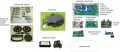
Components overview
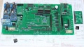
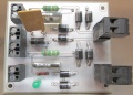
Ardumower PCB connects all modules (available in the shop)
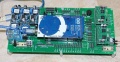
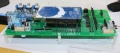
PCB top
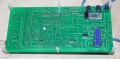
PCB back
PCB and MC33926


Needed modules
All modules can be purchased as complete kits via the shop ![]() .
.
PCB
The printed circuit board (PCB) connects all electronic modules. The PCB is made with the following design parameters:
- PCB dimensions 241x114mm
- All modules (motor driver, Bluetooth, etc.) can be soldered (or plugged) on the PCB (modules are available in the Ardumower shop)
- Uses the Arduino Mega 2560
- Optional: can use Arduino Due via additional adapter PCB
- Optional: integrated charging circuit (current limiting)
- All connections are available on connectors as well as +5V and GND
- Max. trace current (for motors): 8A
PCB building manual
Robot PCB v0.5 (initial prototype, please do not use anymore)
Robot PCB v1.2 (minor layout changes)
- Schematics
- Photos
- Build instructions
- Build instructions (English translation)
- WorkaRound20150527
- WorkaRound20150530
- also see: Documentation in Github
NOTE: The schematics and PCB files were created with KiCad. They can be downloaded from github and can be edited by open source KiCAD software (Download here or here).
PCB building videos
- Resistors
- Diodes and relay
- Capacitors and transistors
- Piezo buzzer and fuse
- Strip pins
- DC/DC converter
- RTC module
- Dual MC33926
- INA169
- Battery & charger
PCB jumpers
| Feature used | YES | NO | Comment |
|---|---|---|---|
| Integrated charging control via adjustable
voltage regulator (LM350T) with potentiometer for adjustable charging voltage (recommended: NO) |
D7: DIODE
D3: DIODE C1, C4, U4, RV1: used |
D7: SHORT-CIRCUIT
D3: SHORT-CIRCUIT C1, C4, U4, RV1: not used |
Do not use if using external battery charger |
| External power while charging (recommended: NO) | JP6: CLOSE
JP7: OPEN D4: DIODE C5: not used |
JP6: OPEN
JP7: CLOSE D4: SHORT-CIRCUIT C5: used |
Use to power your PCB from externally (disconnect battery from PCB) while charging |
| Arduino controlled charge relay (recommended: YES) | JP4: CLOSE
JP5: OPEN |
JP4: OPEN
JP5: CLOSE |
Use for Arduino controlled charge relay (not automatic charging) |
| Arduino Due (3.3V I/O) | LP0, ..., LP15: OPEN | LP0, ..., LP15: CLOSE | Do not use if using Arduino Mega |
| Bluetooth VCC=3.3V | JP8: OPEN
JP9: CLOSE |
JP8: CLOSE
JP9: OPEN |
Many latest modules use 3.3V |
| Bluetooth programming mode | JP2: CLOSE | JP2: OPEN | Use for reprogramming baud rate etc. |
PCB modules
| Module | Feature | Pinout | Optional | Comment |
|---|---|---|---|---|
| U1 | DC/DC converter (10V) | GND, Vout, Vin, GND | No | |
| U2 | Bluetooth (HC-05) | VCC, GND, TXD, RXD, Key, LED | Yes | |
| U3 | Current sensor (charging) | VCC, GND, OUT, IP+, IP-5 | Yes | |
| U4 | Charge control (LM350T) | AJD, OUT, IN | Yes | |
| U5 | Current sensor (charging) | VCC, GND, OUT, IP+, IP-5 | Yes | |
| U6 | DC/DC converter (3.3V) | GND, Vout, Vin, GND | No | |
| U7 | DC/DC converter (5V) | GND, Vout, Vin, GND | No | |
| U8 | Realtime clock (DS1307) | Batt, GND, VCC, SDA, SCL, DS, SQ | Yes | |
| U9 | Wifi (ESP8266) | TX, CH_PD, Reset, VCC, GND, GP_IO2, GP_IO0, RX | Yes | |
| U10 | Level shifter 5V->3V (Arduino Due) | Yes | ||
| U11 | Wifi (ESP8266) | TX, CH_PD, Reset, VCC, GND, GP_IO2, GP_IO0, RX | Yes | alternative mount position |
PCB connectors
| Connector | Feature | Pinout | Optional | Comment |
|---|---|---|---|---|
| P1 | Sonar center (HC SR-04) | 5V, GND, Trigger, Echo | Yes | |
| P2 | Sonar right (HC SR-04) | 5V, GND, Trigger, Echo | Yes | |
| P3 | Sonar left (HC SR-04) | 5V, GND, Trigger, Echo | Yes | |
| P4 | reserved | Yes | ||
| P5 | IMU (gyro,acceleration,compass) (GY-80) | Yes | ||
| P6 | Lawn sensor | Yes | ||
| P7 | Status LEDs | Yes | ||
| P8 | Odometry right | Yes | ||
| P9 | Odometry left | Yes | ||
| P10 | GPS (GY-NEO6MV2) | Yes | ||
| P11 | Bumper | GND, GND, right, left | Yes | |
| P12 | Perimeter coil (center or left) | 5V, GND, perimeter | Yes | |
| P13 | R/C remote control | 5V, GND, mow, steer, speed, switch | Yes | |
| P14 | Measurement points | 5V, GND, (Depending on JP15: 3.3V, 5V or Arduino 3.3V) | Yes | |
| P15 | Wheel motor left | M1OUT1, M1OUT2 | No | |
| P16 | Optional motor driver input | Yes | Do not connect | |
| P17 | Optional motor driver input | Yes | Do not connect | |
| P18 | Wheel motor right | M2OUT1, M2OUT2 | No | |
| P19 | Tilt sensor | 5V, GND, tilt | Yes | |
| P20 | Button (Start/Stop) | No | ||
| P21 | Drop sensor right | Yes | ||
| P22 | Reserved | Yes | ||
| P23 | Reserved | Yes | ||
| P24 | Reserved | Yes | ||
| P25 | Reserved | Yes | ||
| P26 | Reserved | Yes | ||
| P27 | Reserved | Yes | ||
| P28 | Reserved | Yes | ||
| P29 | Reserved | Yes | ||
| P30 | Perimeter coil right | Yes | ||
| P31 | Drop sensor left | Yes | ||
| P32 | GND | Yes | ||
| P33 | 5V | Yes | ||
| P34 | 3.3V | Yes | ||
| P35 | Mower motor RPM | Yes | ||
| P36 | Reserved | Yes | ||
| P37 | Mower motor | No | ||
| P38 | Reserved | Yes | ||
| P39 | Reserved | Yes | ||
| P40 | User switches | Yes | ||
| P41 | Rain sensor | Yes | ||
| P42 | Charging pins | Yes | ||
| P43 | Battery (24V) | No | ||
| P44 | Wifi module (ESP8266) | Yes | ||
| P45 | Reserved | Yes | ||
| P46 | Reserved | Yes |
Power supply
Please also read the section 'Voltages' under Motor driver for more information on motor voltages.
It is recommended to use a voltage step-down converter (e.g. module using LM2596) to generate the 5V voltage for the Arduino and all additional modules. Before connecting, set the voltage of the converter to 5V.
![]() Warning : never connect more than 5V on the Arduino 5V pins, or you will damage the Arduino. Therefore, always measure the 5V voltage before connecting it to the Arduino 5V pin!
All components together (as shown in the schematics) need about 5W power.
Warning : never connect more than 5V on the Arduino 5V pins, or you will damage the Arduino. Therefore, always measure the 5V voltage before connecting it to the Arduino 5V pin!
All components together (as shown in the schematics) need about 5W power.
Motors
Ardumower uses two different types of motors (all motors can be purchased via the shop ![]() ):
):
- Two motors (with integrated gearing) for driving (wheel motors) and with integrated encoders (for distance and speed control)
- One motor (with high rotation speed) for mowing (mower motor)
To control the motors, it requires motor drivers. In addition, the motor driver measures the motor current, and allows us to detect obstacles as motor current increases at obstacles. Ardumower uses two dual MC33926 motor drivers, so two channels for left and right motor and two dual channels (connected in parallel) for the mowing motor.
It is not safe to connect motors directly to the motor driver. Especially, when quickly turning motors from forward to reverse (or vice verse), high voltage spikes appear, and these could damage the motor drivers in the long run. Therefore, we developed driver protector boards that are connected between motor driver and motor.

Voltages
As in all modern systems, Ardumower uses 24V motors.
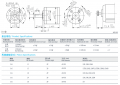
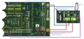
Motor driver assembly (dual MC33926)
Motor driver features: up to 3A with integrated current sensor and thermal shut-down protection
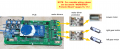
PCB, MC33926, protector and motors
PCB and MC33926
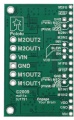
MC33926 pinout
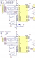
MC33926 schematics


For wiring of motor drivers, protector and motors, please open manual in section Protector PCB.
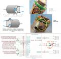
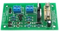
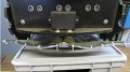
Protector PCB
![]() When quickly tunring motors from forward to backward (or vice versa), high voltage spikes appear. These high voltage spikes could damage the motor driver in the long run. To eliminate high voltage spikes, it is adviced to use a Protector board between motor driver and motor. Two Protector PCBs are required, one for the gear motors, and one for the mowing motor.
When quickly tunring motors from forward to backward (or vice versa), high voltage spikes appear. These high voltage spikes could damage the motor driver in the long run. To eliminate high voltage spikes, it is adviced to use a Protector board between motor driver and motor. Two Protector PCBs are required, one for the gear motors, and one for the mowing motor.
PCB, MC33926, protector and motors
Protector PCB
Protector PCB wiring
Protector PCB schematics


Wheel motors wiring
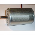
PCB, MC33926, protector and motors
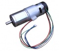
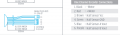
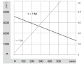
Ardumower gear motor with encoder (8mm diameter, 5900 rpm motor, 0.055 Nm, gear ratio 1/212, output torque 2.45Nm, output rpm 31)
Motor wiring
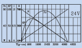
Ardumower gear motor curve (motor only)
Gearbox specification


The two left and right gear motors are controlled independently (aka 'differential driving') to:
- drive the robot forward/backward
- steer the robot left/right
Wheel motor features:
- A rotation speed up to 31 rpm allows to move the robot at sufficient speed (at up to meter/sec = 31rpm/60 * PI * 0.25m = 0.4m/sec using 250mm diameter wheels)
- A high torque (2.45Nm) guarantees that the robot can climb small hills as well (with 2 motors, 0.125 radius wheel, 31rpm = 0.4m/s, acceleration = 0.2 ( 1/2 of nominal speed) see calculator
- Integrated encoders, so it can measure the rotation speed and the distance
- 24V (load current ~1A)
The left gear motor is connected as follows to the protector board:
Motor wiring (left motor):
Motor (black)  ==== Protector board Motor_1_OUT(1)
Motor (red)    ==== Protector board Motor_1_OUT(2)
For right motor, use Protector board Motor_2_OUT(1,2) accordingly.
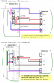
Wheel motors odometry wiring
The Ardumower gear motors have integrated encoders. These encoders help us to compute speed and traveled distance. Here's how you connect the motor odometry wires to the PCB.
Motor wiring
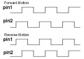
Encoder signal

Motor odometry wiring (left motor):
Motor (brown)  ---- PCB VCC
Motor (green)  ---- PCB GND
Motor (blue)   ---- PCB OdometryLeft (3)
Motor (purple) ---- PCB OdometryLeft (4)
For right motor, use PCB OdometryRight accordingly.
IMPORTANT: PCB v0.5/1.2 are missing pull-up resistors! You need to add them yourself at the PCB:
PCB OdometryLeft(3) --- 4.7k --- 5v
PCB OdometryLeft(4) --- 4.7k --- 5v
Mower motor wiring
PCB, MC33926, protector and motors
Ardumower mower motor
Ardumower mower motor curve
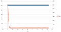
Mower start current
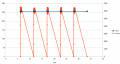
Mower blocked, 500ms detection (max), waittime: 5sec (min)


The Ardumower mower motor features:
- Fast enough to cut the lawn (3150 rpm)
- Enough torque (140 mNm / 46 W)
- Quiet mowing (you cannot hear it)
- 24V, load current ~1.0A (L=2.8mH, R=1.9ohm)
![]() Security note: For security reasons, always remove mower blades in your first tests!
Security note: For security reasons, always remove mower blades in your first tests!
Here's how you connect the mowing motor to the protector board:
Motor (black)  ==== Protector board Motor_1_OUT(1)
Motor (red)    ==== Protector board Motor_1_OUT(2)
Motor decrease noise
Here's how you can decrease motor noise:
Decrease motor noise

Charger
For the charger, we are using a Lithium Ion e-bike charger (29.4V, 1.5A current limitting) that can be purchased via the shop ![]() . The charger is placed in a protected area (house etc.) and connected to the robot charging station. The charger should accomplish the following things (in this case Lithium-Ion, lead battery is similar, but less critical):
. The charger is placed in a protected area (house etc.) and connected to the robot charging station. The charger should accomplish the following things (in this case Lithium-Ion, lead battery is similar, but less critical):
- Charge battery pack via the charging pins of the robot
- Maximum cutoff voltage / charge voltage compliance (charging voltage limit)
- Maximum charging current compliance (charging current limit)
If you are using an existing charger, these things are implemented with high probability already in it. If you don't want to use a charging station, the charger can be connected directly to the Ardumower.
Total power balance
- 2 x Gear motors each 1A (under heavy load): 2A, 27 volt (measured at max. 80% accuracy by motor drivers)
- 1 x Mower motor 1A (under normal load): 1A, 27 volt (measured at max. 80% accuracy by motor drivers)
- PCB: 1A, 5 volt (not measured by PCB)
Total: 3A * 27v + 1A * 5v = 81W + 5W = 86W
Battery

For the battery, we are using a 'Sony Konion 7S2P' Lithium Ion battery pack (Sony Konion US18650V3 2250 mAh cells, Li-Mn), 29.4V x 4500 mAh = 132 Wh, 500 recharge cycles, 126 x 36 x 65 mm (LBH).
Using this battery with the Ardumower motors, the mowing time is about 1.5 hours (132 Wh / 86W).
battery charge/discharge conditions for optimal battery life time:
- charging per cell: max 4.15v (0.3A - 0.1A charging cutt-off)
- discharging per cell: min 3.1v
Here you can see the charging without charging station. If you don't want to use a charging station (or for your first tests), the charger can be connected directly to the Ardumower:

Standby-off / Under-voltage protection
You can add an undervoltage protection to your Ardumower. There are two reasons for a battery switch (standby-off mechanism):
Reason1: If the robot was not started within 5 minutes, it should turn battery off to save energy.
Reason2: Modern batteries should not be completely discharged. When the robot isn't able to charge for some reason and when the battery is below a certain threshold, it should be able to switch off the battery itself (undervoltage protection)
Undervoltage protection PCB
Undervoltage protection PCB wiring


Videos
Bluetooth module
On the robot, you'll need a Bluetooth HC-05 module supporting Bluetooth Serial Port Profile (SPP). SPP uses Bluetooth Service Discovery Protocol (SDP) and the RFCOMM protocol.
Bluetooth HC-05
PCB and HC-05 module
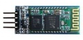
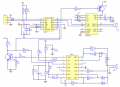
HC-05 module
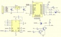
HC-05 schematics


Wiring:
Bluetooth HC05 VCC --- PCB VCC
Bluetooth HC05 GND --- PCB GND
Bluetooth HC05 TX  --- PCB RX
Bluetooth HC05 RX  --- PCB TX
For Programming the Module, you must connect the Key Pin from the BT Module to the 3.3 V from the PCB and disconnect after programming.
Ultrasonic Sensor

An ultrasonic sensor (HC-SR04) allows Ardumower to detect obstacles.
Distance 2 to 450 cm
3x HC-SR04
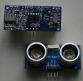
HC-SR04
HC-SR04 schematics


Wiring
Ultrasonic Module VCC (+5V)  — PCB VCC (+5V)
Ultrasonic Module GND        — PCB GND
Ultrasonic Module Trigger    — PCB Digital Pin
Ultrasonic Module Echo       — PCB Digital Pin
An internal schematics of the sensor can be found here.[1]
Rain sensor
Using a rain sensor, your Ardumower can stop mowing when it starts to rain. Additionally, it can drive into your charging station.
NOTE: If using YL-83 module, we have no long-term experience regarding corrosion!
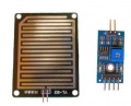
Rain sensor module YL-83
YL-83 schematics
DIY rain sensor


Wiring
                    GND o-----o GND Rain sensor module
                    +5V o-----o VCC Rain sensor module
      Ardumower pinRain o-----o D0  Rain sensor module
                                    Rain sensor module IN o----- rain sensor
                                    Rain sensor module IN o----- rain sensor
Photos


Videos
Further links
GPS


With the help of a GPS receiver (e.g. GY-NEO6MV2, ublox 6m), the long-term position can be calculated. Therefore, the GPS position values will be averaged.
Currently, GPS is used
- to receive current date and time
Wiring:
GPS VCC -- PCB VCC
GPS GND -- PCB GND
GPS TX  -- PCB GPS RX
GPS RX  -- PCB GPS TX
Model R/C
The Ardumower can be controlled via a model R/C. For remote controlling your robot mower you'll need:
- a model remote control (e.g. 2.4 Ghz)
- a suitable model remote receiver (4 channels or more)


Wiring
The channel assignment is:
 left stick (left/right):  pinRemoteSwitch
 left stick (up/down):     pinRemoteMow
 right stick (left/right): pinRemoteSteer
 right stick (up/down):    pinRemoteSpeed
Videos
WIFI

This is an advanced topic - only use a WIFI module if your Ardumower is fully working. A WIFI module can be used as an alternative for Bluetooth communication. Again, pfodApp is required to connect WIFI and the phone.
https://github.com/FredericG-BE/ardumower/wiki/Using-ESP8266-WIFI-module-on-Ardumower
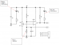
Realtime clock (RTC)
The robot requires a clock, so that it can start mowing automatically at certain time intervals (timer).
A realtime clock (RTC) returns current time (minute, hour) and date (day of week, day, month, year) - by the help of a battery (Lithium Ion LIR2032, 3.6v, 48 mAh) the time continues to run even if the robot mower is switched off.
Additionally, the RTC module contains an EEPROM memory (non volatile memory) that can hold 4K of permanent user data.
DS1307 module
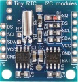
ds1307
ds1307_schematics


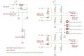
Troubleshooting "Tiny RTC I2C module"
If your module is losing time/date, fix the circuit like this:
- Remove D1, R6 and R4
- Solder jumper wire in place of R6
- Inspect crystal soldering - fix if necessary
- Replace battery
Wiring
The RTC module is connected on the I2C bus of the Arduino Mega (in parallel with any other I2C modules).
 DS1307 Module SDA       — Arduino SDA Pin
 DS1307 Module SCL       — Arduino SCL Pin
 DS1307 Module VCC (+5V) — Arduino VCC (+5V)
 DS1307 Module GND       — Arduino GND
Note
If you experience communication problems when using multiple I2C modules on one I2C bus, it is recommended to reduce the length of the cables.
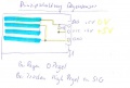
Arduino Dropsensor - Absturzsensor
Funktion:
Der Arduino Dropsensor oder auch Absturzsensor ist dafür gedacht den Mover vor abstürzen vor Treppenabsätzen oder ähnlichen zu schützen. Ebenso kann dieser eingesetzt werden um Inseln von Bäumen und Blumenbeeten zu erkennen. Voraussetzung dafür ist allerdings das dieser an der Graskante hin zur Insel mit einem kleinen Graben umgeben wird damit dieser zuverlässig erkannt werden
Anschluß:
Benötigt werden 2 IR Entfernungssensoren. Am besten sind solche geeignet die bereits in einem externen Gehäuse eingebaut sind. Diese haben auch auf der Rückseite eine Einstellmöglichkeit für die Entfernung bzw Empfindlichkeit. Die Standard Ausführung benötigt 3 Anschlussleitungen . +5V, GND, Signalleitung und haben eine Empfindlichkeit von ca 30mm – 800mm. Bei den Sensor den ich verwende handelt es sich um einen der gegen GND geschaltet wird. Dort habe ich zusätzlich eine Diode in die Signalleitung mit eingebaut um eventuelle positive Spannungen zum Bord zu blockieren und um einen eindeutigen Schaltzustand zu gewährleisten.

ohne eingbaute Diode
IR leuchtet bei Kontakt zur Oberfläche
Messung:
+ nach Signalausgang = 4,96V
- nach Signalausgang = 0V
IR leuchtet nicht über den Abgrund
Messung:
+ nach Signalausgang = 0V
- nach Signalausgang = 3,72V ( das hat mich gestört ) deshalb habe ich die Diode eingebaut
jetzt das ganze mit Diode in der Signalleitung
IR leuchtet bei Kontakt zur Oberfläche
Messung:
+ nach Signalausgang = 4,7V
- nach Signalausgang = 0V
IR leuchtet nicht über den Abgrund
Messung:
+ nach Signalausgang = 0V
- nach Signalausgang = 0V
jetzt 0V gemessen zwischen - und Signalausgang
Ich hatte bedenken gehabt das die 3,72V ein undefinierten Eingang schaffen was evl Probleme bei der Auswertung geben könnte.
Bekannte Probleme:
Ich habe die Beobachtung gemacht das wenn man die Entfernungseinstellung auf den Gras gegebenenfalls noch nach justiert werden muss. Ebenfalls ist mir aufgefallen das wenn die Sensoren auf eine nasse Betonoberfläche stoßen, irrtümlich annehmen das ein Abgrund erkannt wird. Da ich an meinen Testmower die Sensoren nur provisorisch angebracht habe, kann ich mir vorstellen das Fremdlicht zu Problemen in der Erkennung führt. Ich vermute daher, das wenn man die Sensoren vor Fremdlicht schützt, sich die Zuverlässigkeit auch weiter erhöht.
Evl ist es nötig mit Hilfe einer LED die Fläche zu beleuchten um immer eine gleichmäßige Helligkeit zu gewährleisten.
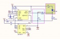
Relay

Using a relay, you can switch on/off external functions (light, horn etc.) on your Ardumower via pfodApp.
Wiring
                      GND o-----o GND Relais module
                      +5V o-----o VCC Relais module
 Ardumower pinUserSwitch1 o-----o IN1 Relais module
                                      Relais module  K1 o-----LED-----o LED supply voltage
                                      Relais module  K1 o-------------o GND
Pictures

Illuminated lawn
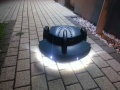
Ardumower lights

