Perimeter wire: Unterschied zwischen den Versionen
(→Perimeter v1 (v0.9.3)) |
|||
| Zeile 88: | Zeile 88: | ||
Important: When using this amplifier, capacitor C3 should be bypassed (will give a VCC/2 offset required for Arduino) and the coil will be connected to "IN" and "GND". | Important: When using this amplifier, capacitor C3 should be bypassed (will give a VCC/2 offset required for Arduino) and the coil will be connected to "IN" and "GND". | ||
| + | |||
| + | ====Functional test==== | ||
| + | # Make sure that the sender works correctly (see further above). | ||
| + | # Increase the Arduino Sound Sensor potentiometer to maximum (rotate counter-clock-wise). | ||
| + | # After uploading the code, move one coil towards the perimeter wire. The Arduino LED should start to blink. Now, hold both coils at same distance over the perimeter wire. The Arduino LED should be always ON now. | ||
| + | # If that doesn't work, open the serial console (19200 baud), and verify the signal values. | ||
| + | |||
| + | ====Choice for coil==== | ||
| + | Induction math, only approximation: | ||
| + | |||
| + | L = 1nH x n² x ((D² / mm² ) / (l / mm)) | ||
| + | l = coil length | ||
| + | D = coil diameter | ||
| + | |||
| + | Example: An inductance of 85 mH, and diamter of 10 mm, and length of 40 mm require about 5830 windings. | ||
| + | |||
| + | This inductance of 85 mH results in a capacity of 4.7 nF and a resonation frequency of 7963 kHz. | ||
| + | |||
| + | Because it's sometimes difficult to find a specific coil, here are possible combinations (coil / capacitor) you can use (all will have a resonation frequency of 7.8 Khz): | ||
| + | Combination 1: Coil: 85mH, Capacitor: 4.7nF (tested) | ||
| + | Combination 2: Coil 104mH, Capacitor: 4nF (tested) | ||
| + | |||
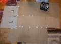
| + | ====Arrangement of coils==== | ||
| + | The coils are arranged at the bottom of the robot, about 90 degress to each other, both turned 45 degress. | ||
| + | <gallery> | ||
| + | File: Ardumower_spulen.jpg | ||
| + | File: L50_coils.jpg |Example (Ambrogio L50) | ||
| + | File: L50_parcours.jpg | ||
| + | </gallery> | ||
| + | |||
| + | ====Measurements of signal strength==== | ||
| + | To compare measurements, the signal strength has been determined at several distances. The signal strength (i.e. the calculated ADC value) is shown in the Android pfodApp. The distance (cm) is the length calculated from the perimeter loop until the coil (coil built-in the robot). | ||
| + | |||
| + | <gallery> | ||
| + | File: Perimeter_plot.png | ||
| + | </gallery> | ||
| + | |||
| + | ====Layout of the wire==== | ||
| + | |||
| + | It's important that the wire layout is round and does not have corners! Let's assume that the wire has a corner, and the robots drives exactly over the corner, it will not be able to detect the wire as both wire and coils are aligned (also see section before). | ||
| + | |||
| + | <gallery> | ||
| + | File: Schleifen_blind.jpg | ||
| + | File: Ardumower_coil_signal.png| How does the signal change when rotating the coil? | ||
| + | </gallery> | ||
==Perimeter v2 (SVN version)== | ==Perimeter v2 (SVN version)== | ||
Version vom 12. September 2014, 13:03 Uhr
Inhaltsverzeichnis
Abstract
A perimeter wire (or buried wire fence, BWF) is like a 'virtual fence': it stopps the robot when it reaches its boundaries. A perimeter is not always necessary for all surroundings (a lawn sensor might be an alternative).
Principle idea: You will install a perimeter loop (a wire) in your garden through which a signal is sent and this signal is detected by the robot. So, you'll need: a sender (to transmit the on the wire) and a receiver (to detect the signal in the robot).
How is the signal detected? The signal is detected by one (or two) receiver coils. The closer the distance between coil and perimeter loop, the higher the signal. Also, something interesting happens when the robot crosses the perimeter loop: the signal changes its polarity, that means positive and negative voltages reverse each other. So, there are two basic principles to detect the perimeter loop. We have implemented both methods (perimeter v1 and v2) which are described below.

Perimeter v1 (v0.9.3)
Sender
You can use the sender of a commercial lawn robot (the sender shown here is compatible with Tianchen or Rotenbach robot mowers), or you build one yourself.
So, here's the sender:
An Arduino (e.g. Nano) generates a square signal that is used to switch the direction of a motor driver (L298N) at 7.8 Khz. Thereby, the motor driver will switch the output between VCC and GND. A resonator circuit amplifies the signal spikes as it's dimensioned so that its resonation frequency is the same as the switching frequency (7.8 Khz). That way, the motor drive only needs to be operated at 5V (instead of 12V). The power supply should be able to supply 2W (400mA at 5V). One part of the signal is captured by the Arduino (ADC) through a diode and a voltage divider. This allows to detect if the perimeter loop is connected or not. A 150 mA current will flow through in the perimeter wire (wire cross section 2-3 mm^2) - the wire should not be longer than 500m.

Because it's sometimes difficult to find a specific coil, here are possible combinations (coil / capacitor) you can use (all will have a resonation frequency of 7.8 Khz):
- Combination 1: Coil: 160µH, Capacitor: 3,3µF/50V (tested)
- Combination 2: Coil 33mH, Capacitor: 12nF (not tested)
Power supply
It is recommended to use a voltage step-down converter (e.g. module using LM2596) to generate the 5V voltage. Before connecting, set the voltage of the converter to 5V. Warning : never connect more than 5V on the Arduino 5V pins, or you will damage the Arduino. Therefore, always measure the 5V voltage before connecting it to the Arduino 5V pin!
Functional test
1. After uploading the code and connecting the perimeter wire, the Arduino LED should be ON. Now remove the perimeter wire - the Arduino LED should go OFF. 2. If that doesn't work: Using a voltmeter, measure once at Arduino pin D9 and once at motor driver output pin (OUT_1) against ground - both should have a DC voltage of 2.5 Volt. 3. If you have an oscilloscope, replace the perimeter wire by the oscilloscope. The measured signal look like below:
The output signal shows a higher amplitude (high spikes) as the input signal:
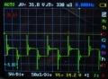
signal on the sender output
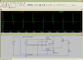
resonator circuit basic principle


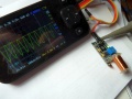
For a simple receiver test, you can simply connect the receiver coil to an oscilloscope. The measured oscilloscope signal should look like below:
This signal can be detected easily with a coil:
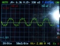
coil signal at receiver coil
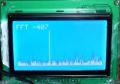
signal in frequency spectrum, superposed by motor noise
frequency spectrum via pfodApp


Receiver
The receiver uses 2 coils mounted left and right in the robot. The signal strenght of left and right coils is evaluated to be able to compare them.
Principle:
- Amplification of alternating signal using OPAMP
- Optional: Bandpass-filtering to filter-out noise caused by motors etc.
- Evaluation of signal strength of left and right coil
Advantage of this version: analog controlling works great. Disadvantage: You cannot detect, where you are (inside/outside) if your missed the perimter crossing. Also, you cannot detect if you drive clockwise or anti-clockwise on the perimeter wire.

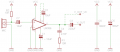
A coil receives the sender's signal. A resonator circuit (LC) amplifies the received signal at resonation frequency (7.8 kHz). Then the signal is amplified using an LM386 (here: Arduino sound sensor using coil instead of microphone). A bandpass-filter (digital filter, FFT) on the Arduino filters the desired frequency (7.8 Khz) and outputs a PWM signal (pulse width is proportional to signal strength). A lowpass-filter converts it to a DC voltage. Note: Wiring between Nano and Mega has been simplified - see schematics for exact wiring.
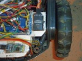
We have tested the following combinations of amplifier und coils:
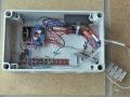
Amplifying signal using LM386 - Arduino Sound Sensor using coil instead microphone
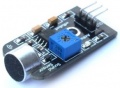
Arduino Sound Sensor using LM386
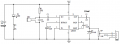
Arduino Sound Sensor schematics
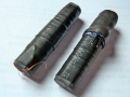
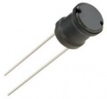
85 mH coils


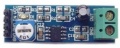
LM386 amplifier (200x amplification)
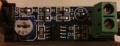
LM386 circuit
104 mH coil


Important: When using this amplifier, capacitor C3 should be bypassed (will give a VCC/2 offset required for Arduino) and the coil will be connected to "IN" and "GND".
Functional test
- Make sure that the sender works correctly (see further above).
- Increase the Arduino Sound Sensor potentiometer to maximum (rotate counter-clock-wise).
- After uploading the code, move one coil towards the perimeter wire. The Arduino LED should start to blink. Now, hold both coils at same distance over the perimeter wire. The Arduino LED should be always ON now.
- If that doesn't work, open the serial console (19200 baud), and verify the signal values.
Choice for coil
Induction math, only approximation:
L = 1nH x n² x ((D² / mm² ) / (l / mm)) l = coil length D = coil diameter
Example: An inductance of 85 mH, and diamter of 10 mm, and length of 40 mm require about 5830 windings.
This inductance of 85 mH results in a capacity of 4.7 nF and a resonation frequency of 7963 kHz.
Because it's sometimes difficult to find a specific coil, here are possible combinations (coil / capacitor) you can use (all will have a resonation frequency of 7.8 Khz): Combination 1: Coil: 85mH, Capacitor: 4.7nF (tested) Combination 2: Coil 104mH, Capacitor: 4nF (tested)
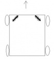
Arrangement of coils
The coils are arranged at the bottom of the robot, about 90 degress to each other, both turned 45 degress.
Example (Ambrogio L50)


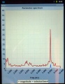
Measurements of signal strength
To compare measurements, the signal strength has been determined at several distances. The signal strength (i.e. the calculated ADC value) is shown in the Android pfodApp. The distance (cm) is the length calculated from the perimeter loop until the coil (coil built-in the robot).

Layout of the wire
It's important that the wire layout is round and does not have corners! Let's assume that the wire has a corner, and the robots drives exactly over the corner, it will not be able to detect the wire as both wire and coils are aligned (also see section before).
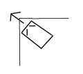
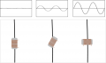
How does the signal change when rotating the coil?


Perimeter v2 (SVN version)
Sender
...
Receiver
...