Wheel Motor: Unterschied zwischen den Versionen
(→Motors testing) |
|||
| (7 dazwischenliegende Versionen desselben Benutzers werden nicht angezeigt) | |||
| Zeile 19: | Zeile 19: | ||
= Wiring = | = Wiring = | ||
| − | + | Using motor driver MC33926 : | |
| + | Right | Left | ||
| + | |||
| + | Pin 33 | Pin 31 One pin controls the direction (forward/backward) | ||
| + | |||
| + | Pin 03 | Pin 05 the other pin controls the speed. | ||
| + | |||
| + | Pin A0 | Pin A1 One analog input pin is connected to the current sensor. | ||
| + | |||
| + | Pin 27 | Pin 25 input pin to read fault | ||
| + | |||
| + | <gallery> | ||
| + | File:MC33926_schematics.jpg | schematics | ||
| + | </gallery> | ||
| + | |||
| + | |||
| + | [https://github.com/Ardumower/ardumower/raw/master/pcb/megashield_svn_1.2_geschlossen/Dokumentation/WORKSHOP%20Protector-Board.pdf Protector board] is adviced to be used between controler and motor. | ||
| + | |||
| + | == Alternative solution == | ||
| + | |||
| + | The current sensor module (ACS712-05A) is connected in series with the motor. | ||
<gallery> | <gallery> | ||
File:Ardumower_motor_driver_circuit.png | NOTE: only for demonstration! See real [http://wiki.ardumower.de/index.php?title=Ardumower_PCB schematics] for concrete wiring | File:Ardumower_motor_driver_circuit.png | NOTE: only for demonstration! See real [http://wiki.ardumower.de/index.php?title=Ardumower_PCB schematics] for concrete wiring | ||
</gallery> | </gallery> | ||
| − | |||
== Control principal : PWM frequency == | == Control principal : PWM frequency == | ||
| Zeile 42: | Zeile 61: | ||
<gallery> | <gallery> | ||
| + | File:Speedcontrol.png | Motor speed settings | ||
File: Odometry_motor_pid_controller.png | File: Odometry_motor_pid_controller.png | ||
</gallery> | </gallery> | ||
| Zeile 47: | Zeile 67: | ||
= Programming = | = Programming = | ||
| − | / | + | == Motor variables == |
| + | |||
| + | // --------- wheel motor state ---------------------------- | ||
| + | // wheel motor speed ( <0 backward, >0 forward); range -motorSpeedMaxRpm..motorSpeedMaxRpm | ||
| + | // [Default value] | ||
| + | float motorAccel ; // motor wheel acceleration - only functional when odometry is not in use | ||
| + | // (warning: do not set too high) [1000] | ||
| + | int motorSpeedMaxRpm ; // motor wheel max RPM [25] | ||
| + | int motorSpeedMaxPwm ; // motor wheel max Pwm (8-bit PWM=255, 10-bit PWM=1023) [255] | ||
| + | float motorPowerMax ; // motor wheel max power (Watt) | ||
| + | PID motorLeftPID; // motor left wheel PID controller [Kp=1.5 , Kd=0.29, Ki=0.25] | ||
| + | PID motorRightPID; // motor right wheel PID controller | ||
| + | float motorSenseRightScale ; // motor right sense scale (mA=(ADC-zero)/scale) | ||
| + | float motorSenseLeftScale ; // motor left sense scale (mA=(ADC-zero)/scale) | ||
| + | int motorRollTimeMax ; // max. roll time (ms) | ||
| + | int motorRollTimeMin ; // min. roll time (ms) | ||
| + | int motorReverseTime ; // max. reverse time (ms) | ||
| + | long motorForwTimeMax; // max. forward time (ms) / timeout | ||
| + | float motorBiDirSpeedRatio1 ;// bidir mow pattern speed ratio 1 | ||
| + | float motorBiDirSpeedRatio2 ;// bidir mow pattern speed ratio 2 | ||
| + | bool motorRightSwapDir ; // inverse right motor direction? | ||
| + | bool motorLeftSwapDir ; // inverse left motor direction? | ||
| + | int motorLeftSpeedRpmSet ; // set speed | ||
| + | int motorRightSpeedRpmSet ; | ||
| + | float motorLeftPWMCurr ; // current speed | ||
| + | float motorRightPWMCurr ; | ||
| + | int motorRightSenseADC ; | ||
| + | int motorLeftSenseADC ; | ||
| + | float motorLeftSenseCurrent ; | ||
| + | float motorRightSenseCurrent ; | ||
| + | float motorLeftSense ; // motor power (range 0..MAX_MOTOR_POWER) | ||
| + | float motorRightSense ; | ||
| + | int motorPowerIgnoreTime; | ||
| + | int motorZeroSettleTime; // how long (ms) to wait for motor to settle at zero speed | ||
| + | int motorLeftSenseCounter ; // motor current counter | ||
| + | int motorRightSenseCounter ; | ||
| + | unsigned long nextTimeMotorSense ; | ||
| + | unsigned long lastSetMotorSpeedTime; | ||
| + | unsigned long motorLeftZeroTimeout; | ||
| + | unsigned long motorRightZeroTimeout; | ||
| + | boolean rotateLeft; | ||
| + | unsigned long nextTimeRotationChange; | ||
| + | |||
| + | == Motor Methods == | ||
| + | |||
| + | First the basic function that control the pwm to each motors: | ||
| + | void setMotorPWM(int pwmLeft, int pwmRight, boolean useAccel); | ||
| + | |||
| + | A general methods to test motors | ||
| + | void testMotors(); | ||
| + | |||
| + | Then, there are several MotorControl methods according to mower state : | ||
| + | |||
| + | if current state is 'STATE_PERI_TRACK' then | ||
| + | void motorControlPerimeter(); | ||
| + | |||
| + | |||
| + | void motorControlImuRoll(); | ||
| + | |||
| + | void motorControlImuDir(); | ||
| + | |||
| + | for all other case : | ||
| + | |||
| + | void motorControl(); | ||
| + | // This method calculate pwm to set in order to respect rpm setpoint according current rpm and Kp, Ki, Kd parameter | ||
| + | |||
| + | = Motors testing = | ||
| + | |||
| + | Run the serial console (Arduino IDE: CTRL+SHIFT+M, 19200 Baud) and press 'd' and ENTER for menu. | ||
| + | Then press '1' and ENTER to run the motor test. | ||
| + | |||
| + | Test consist of the following sequence : | ||
| + | |||
| + | * Left motor : Forward half speed | ||
| + | |||
| + | * Left motor : Reverse full speed | ||
| + | |||
| + | * Right motor : Forward half speed | ||
| + | |||
| + | * Right motor : Reverse full speed | ||
| + | |||
| + | |||
| + | NB : If motor rotation is inverse to what is expected, then you need to switch the wiring at the outlet of motor controller. | ||
Aktuelle Version vom 2. Januar 2016, 13:17 Uhr
Inhaltsverzeichnis
Wheel motors caracteristics & driver
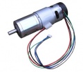
Ardumower gear motor with encoder (8mm diameter, 5900 rpm motor, 0.055 Nm, gear ratio 1/212, output torque 2.45Nm, output rpm 31)
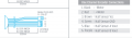
Motor wiring
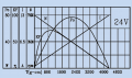
Ardumower gear motor curve (motor only)
Decrease motor noise


The two left and right gear motors are controlled independently (aka 'differential driving') to:
- drive the robot forward/backward
- steer the robot left/right
The Ardumower wheel motor features:
- A rotation speed up to 31 rpm allows to move the robot at sufficient speed (at up to meter/sec = 31rpm/60 * PI * 0.25m = 0.4m/sec using 250mm diameter wheels)
- A high torque (2.45Nm) guarantees that the robot can climb small hills as well (with 2 motors, 0.125 radius wheel, 31rpm = 0.4m/s, acceleration = 0.2 ( 1/2 of nomeinal speed) up to 14 degree) see calculator
- Integrated encoders, so it can measure the rotation speed, the distance and the direction (see Odometry for more information) - Encoders are REQUIRED for Ardumower software.
- 24V (load current ~1A)
Wiring
Using motor driver MC33926 :
Right | Left
Pin 33 | Pin 31 One pin controls the direction (forward/backward)
Pin 03 | Pin 05 the other pin controls the speed.
Pin A0 | Pin A1 One analog input pin is connected to the current sensor.
Pin 27 | Pin 25 input pin to read fault
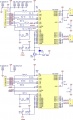
schematics

Protector board is adviced to be used between controler and motor.
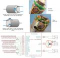
Alternative solution
The current sensor module (ACS712-05A) is connected in series with the motor.
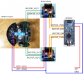
NOTE: only for demonstration! See real schematics for concrete wiring

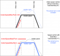
Control principal : PWM frequency
The speed of the motor is controlled by a PWM duty signal. We use the Arduino default PWM frequency (490 Hz) to control the motor drivers.

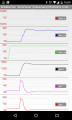
Arduino PWM duty signal
PWM 490 Hz: odometry ticks, sense (current)
PWM 3.9 Khz: odometry ticks, sense (current)
PWM 20 Khz: odometry ticks, sense (current)
PWM 31 Khz: odometry ticks, sense (current)


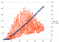
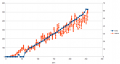
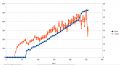
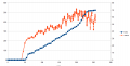
Motor controller (PID)
The speed of the motors is controlled by a software PID controller. You can monitor the quality of the motor speed control via pfodApp (Plot->Motor control):
Motor speed settings


Programming
Motor variables
   // --------- wheel motor state ----------------------------
   // wheel motor speed ( <0 backward, >0 forward); range -motorSpeedMaxRpm..motorSpeedMaxRpm
   //                                   [Default value]
   float motorAccel  ;          // motor wheel acceleration - only functional when odometry is not in use
                                // (warning: do not set too high) [1000]
   int motorSpeedMaxRpm   ;     // motor wheel max RPM  [25]
   int motorSpeedMaxPwm  ;      // motor wheel max Pwm  (8-bit PWM=255, 10-bit PWM=1023) [255]
   float motorPowerMax   ;      // motor wheel max power (Watt)
   PID motorLeftPID;            // motor left wheel PID controller [Kp=1.5 , Kd=0.29, Ki=0.25]
   PID motorRightPID;           // motor right wheel PID controller
   float motorSenseRightScale ; // motor right sense scale (mA=(ADC-zero)/scale)
   float motorSenseLeftScale ;  // motor left sense scale  (mA=(ADC-zero)/scale)
   int motorRollTimeMax ;       // max. roll time (ms)
   int motorRollTimeMin  ;      // min. roll time (ms)
   int motorReverseTime ;       // max. reverse time (ms)
   long motorForwTimeMax;       // max. forward time (ms) / timeout
   float motorBiDirSpeedRatio1 ;// bidir mow pattern speed ratio 1
   float motorBiDirSpeedRatio2 ;// bidir mow pattern speed ratio 2
   bool motorRightSwapDir     ; // inverse right motor direction?
   bool motorLeftSwapDir      ; // inverse left motor direction?
   int motorLeftSpeedRpmSet ;   // set speed
   int motorRightSpeedRpmSet ;
   float motorLeftPWMCurr ;     // current speed
   float motorRightPWMCurr ;
   int motorRightSenseADC ;
   int motorLeftSenseADC ;
   float motorLeftSenseCurrent ;
   float motorRightSenseCurrent ;
   float motorLeftSense ;       // motor power (range 0..MAX_MOTOR_POWER)
   float motorRightSense ;
   int motorPowerIgnoreTime;
   int motorZeroSettleTime;     // how long (ms) to wait for motor to settle at zero speed
   int motorLeftSenseCounter ;  // motor current counter
   int motorRightSenseCounter ;
   unsigned long nextTimeMotorSense ;
   unsigned long lastSetMotorSpeedTime;
   unsigned long motorLeftZeroTimeout;
   unsigned long motorRightZeroTimeout;
   boolean rotateLeft;
   unsigned long nextTimeRotationChange;
Motor Methods
First the basic function that control the pwm to each motors:
void setMotorPWM(int pwmLeft, int pwmRight, boolean useAccel);
A general methods to test motors
void testMotors();
Then, there are several MotorControl methods according to mower state :
if current state is 'STATE_PERI_TRACK' then
void motorControlPerimeter();
void motorControlImuRoll();
void motorControlImuDir();
for all other case :
 void motorControl();
 // This method calculate pwm to set in order to respect rpm setpoint according current rpm and Kp, Ki, Kd parameter
Motors testing
Run the serial console (Arduino IDE: CTRL+SHIFT+M, 19200 Baud) and press 'd' and ENTER for menu. Then press '1' and ENTER to run the motor test.
Test consist of the following sequence :
- Left motor : Forward half speed
- Left motor : Reverse full speed
- Right motor : Forward half speed
- Right motor : Reverse full speed
NB : If motor rotation is inverse to what is expected, then you need to switch the wiring at the outlet of motor controller.