Wheel Motor: Unterschied zwischen den Versionen
(→Motor controller (PID)) |
(→Motors testing) |
||
| (4 dazwischenliegende Versionen desselben Benutzers werden nicht angezeigt) | |||
| Zeile 19: | Zeile 19: | ||
= Wiring = | = Wiring = | ||
| − | One pin controls the direction (forward/backward) | + | Using motor driver MC33926 : |
| + | |||
| + | Right | Left | ||
| + | |||
| + | Pin 33 | Pin 31 One pin controls the direction (forward/backward) | ||
| + | |||
| + | Pin 03 | Pin 05 the other pin controls the speed. | ||
| + | |||
| + | Pin A0 | Pin A1 One analog input pin is connected to the current sensor. | ||
| + | |||
| + | Pin 27 | Pin 25 input pin to read fault | ||
<gallery> | <gallery> | ||
| − | File: | + | File:MC33926_schematics.jpg | schematics |
</gallery> | </gallery> | ||
| + | |||
[https://github.com/Ardumower/ardumower/raw/master/pcb/megashield_svn_1.2_geschlossen/Dokumentation/WORKSHOP%20Protector-Board.pdf Protector board] is adviced to be used between controler and motor. | [https://github.com/Ardumower/ardumower/raw/master/pcb/megashield_svn_1.2_geschlossen/Dokumentation/WORKSHOP%20Protector-Board.pdf Protector board] is adviced to be used between controler and motor. | ||
| + | |||
| + | == Alternative solution == | ||
| + | |||
| + | The current sensor module (ACS712-05A) is connected in series with the motor. | ||
| + | <gallery> | ||
| + | File:Ardumower_motor_driver_circuit.png | NOTE: only for demonstration! See real [http://wiki.ardumower.de/index.php?title=Ardumower_PCB schematics] for concrete wiring | ||
| + | </gallery> | ||
| + | |||
== Control principal : PWM frequency == | == Control principal : PWM frequency == | ||
| Zeile 48: | Zeile 67: | ||
= Programming = | = Programming = | ||
| − | == Motor | + | == Motor variables == |
// --------- wheel motor state ---------------------------- | // --------- wheel motor state ---------------------------- | ||
// wheel motor speed ( <0 backward, >0 forward); range -motorSpeedMaxRpm..motorSpeedMaxRpm | // wheel motor speed ( <0 backward, >0 forward); range -motorSpeedMaxRpm..motorSpeedMaxRpm | ||
| − | float motorAccel ; | + | // [Default value] |
| − | int motorSpeedMaxRpm ; | + | float motorAccel ; // motor wheel acceleration - only functional when odometry is not in use |
| − | int motorSpeedMaxPwm ; | + | // (warning: do not set too high) [1000] |
| − | float motorPowerMax ; | + | int motorSpeedMaxRpm ; // motor wheel max RPM [25] |
| − | PID motorLeftPID; | + | int motorSpeedMaxPwm ; // motor wheel max Pwm (8-bit PWM=255, 10-bit PWM=1023) [255] |
| − | PID motorRightPID; | + | float motorPowerMax ; // motor wheel max power (Watt) |
| + | PID motorLeftPID; // motor left wheel PID controller [Kp=1.5 , Kd=0.29, Ki=0.25] | ||
| + | PID motorRightPID; // motor right wheel PID controller | ||
float motorSenseRightScale ; // motor right sense scale (mA=(ADC-zero)/scale) | float motorSenseRightScale ; // motor right sense scale (mA=(ADC-zero)/scale) | ||
| − | float motorSenseLeftScale ; // motor left sense scale (mA=(ADC-zero)/scale) | + | float motorSenseLeftScale ; // motor left sense scale (mA=(ADC-zero)/scale) |
| − | int motorRollTimeMax ; | + | int motorRollTimeMax ; // max. roll time (ms) |
| − | int motorRollTimeMin ; // min. roll time (ms) | + | int motorRollTimeMin ; // min. roll time (ms) |
| − | int motorReverseTime ; | + | int motorReverseTime ; // max. reverse time (ms) |
| − | long motorForwTimeMax; // max. forward time (ms) / timeout | + | long motorForwTimeMax; // max. forward time (ms) / timeout |
| − | float motorBiDirSpeedRatio1 ; | + | float motorBiDirSpeedRatio1 ;// bidir mow pattern speed ratio 1 |
| − | float motorBiDirSpeedRatio2 ; | + | float motorBiDirSpeedRatio2 ;// bidir mow pattern speed ratio 2 |
| − | bool motorRightSwapDir ; | + | bool motorRightSwapDir ; // inverse right motor direction? |
| − | bool motorLeftSwapDir ; | + | bool motorLeftSwapDir ; // inverse left motor direction? |
| − | int motorLeftSpeedRpmSet ; // set speed | + | int motorLeftSpeedRpmSet ; // set speed |
int motorRightSpeedRpmSet ; | int motorRightSpeedRpmSet ; | ||
| − | float motorLeftPWMCurr ; // current speed | + | float motorLeftPWMCurr ; // current speed |
float motorRightPWMCurr ; | float motorRightPWMCurr ; | ||
int motorRightSenseADC ; | int motorRightSenseADC ; | ||
| Zeile 76: | Zeile 97: | ||
float motorLeftSenseCurrent ; | float motorLeftSenseCurrent ; | ||
float motorRightSenseCurrent ; | float motorRightSenseCurrent ; | ||
| − | float motorLeftSense ; | + | float motorLeftSense ; // motor power (range 0..MAX_MOTOR_POWER) |
float motorRightSense ; | float motorRightSense ; | ||
int motorPowerIgnoreTime; | int motorPowerIgnoreTime; | ||
| Zeile 88: | Zeile 109: | ||
boolean rotateLeft; | boolean rotateLeft; | ||
unsigned long nextTimeRotationChange; | unsigned long nextTimeRotationChange; | ||
| + | |||
| + | == Motor Methods == | ||
| + | |||
| + | First the basic function that control the pwm to each motors: | ||
| + | void setMotorPWM(int pwmLeft, int pwmRight, boolean useAccel); | ||
| + | |||
| + | A general methods to test motors | ||
| + | void testMotors(); | ||
| + | |||
| + | Then, there are several MotorControl methods according to mower state : | ||
| + | |||
| + | if current state is 'STATE_PERI_TRACK' then | ||
| + | void motorControlPerimeter(); | ||
| + | |||
| + | |||
| + | void motorControlImuRoll(); | ||
| + | |||
| + | void motorControlImuDir(); | ||
| + | |||
| + | for all other case : | ||
| + | |||
| + | void motorControl(); | ||
| + | // This method calculate pwm to set in order to respect rpm setpoint according current rpm and Kp, Ki, Kd parameter | ||
| + | |||
| + | = Motors testing = | ||
| + | |||
| + | Run the serial console (Arduino IDE: CTRL+SHIFT+M, 19200 Baud) and press 'd' and ENTER for menu. | ||
| + | Then press '1' and ENTER to run the motor test. | ||
| + | |||
| + | Test consist of the following sequence : | ||
| + | |||
| + | * Left motor : Forward half speed | ||
| + | |||
| + | * Left motor : Reverse full speed | ||
| + | |||
| + | * Right motor : Forward half speed | ||
| + | |||
| + | * Right motor : Reverse full speed | ||
| + | |||
| + | |||
| + | NB : If motor rotation is inverse to what is expected, then you need to switch the wiring at the outlet of motor controller. | ||
Aktuelle Version vom 2. Januar 2016, 13:17 Uhr
Inhaltsverzeichnis
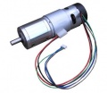
Wheel motors caracteristics & driver
The two left and right gear motors are controlled independently (aka 'differential driving') to:
- drive the robot forward/backward
- steer the robot left/right
The Ardumower wheel motor features:
- A rotation speed up to 31 rpm allows to move the robot at sufficient speed (at up to meter/sec = 31rpm/60 * PI * 0.25m = 0.4m/sec using 250mm diameter wheels)
- A high torque (2.45Nm) guarantees that the robot can climb small hills as well (with 2 motors, 0.125 radius wheel, 31rpm = 0.4m/s, acceleration = 0.2 ( 1/2 of nomeinal speed) up to 14 degree) see calculator
- Integrated encoders, so it can measure the rotation speed, the distance and the direction (see Odometry for more information) - Encoders are REQUIRED for Ardumower software.
- 24V (load current ~1A)
Wiring
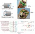
Using motor driver MC33926 :
Right | Left
Pin 33 | Pin 31 One pin controls the direction (forward/backward)
Pin 03 | Pin 05 the other pin controls the speed.
Pin A0 | Pin A1 One analog input pin is connected to the current sensor.
Pin 27 | Pin 25 input pin to read fault
Protector board is adviced to be used between controler and motor.
Alternative solution
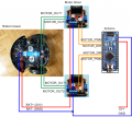
The current sensor module (ACS712-05A) is connected in series with the motor.
NOTE: only for demonstration! See real schematics for concrete wiring
Control principal : PWM frequency
The speed of the motor is controlled by a PWM duty signal. We use the Arduino default PWM frequency (490 Hz) to control the motor drivers.
Motor controller (PID)
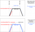
The speed of the motors is controlled by a software PID controller. You can monitor the quality of the motor speed control via pfodApp (Plot->Motor control):
Programming
Motor variables
   // --------- wheel motor state ----------------------------
   // wheel motor speed ( <0 backward, >0 forward); range -motorSpeedMaxRpm..motorSpeedMaxRpm
   //                                   [Default value]
   float motorAccel  ;          // motor wheel acceleration - only functional when odometry is not in use
                                // (warning: do not set too high) [1000]
   int motorSpeedMaxRpm   ;     // motor wheel max RPM  [25]
   int motorSpeedMaxPwm  ;      // motor wheel max Pwm  (8-bit PWM=255, 10-bit PWM=1023) [255]
   float motorPowerMax   ;      // motor wheel max power (Watt)
   PID motorLeftPID;            // motor left wheel PID controller [Kp=1.5 , Kd=0.29, Ki=0.25]
   PID motorRightPID;           // motor right wheel PID controller
   float motorSenseRightScale ; // motor right sense scale (mA=(ADC-zero)/scale)
   float motorSenseLeftScale ;  // motor left sense scale  (mA=(ADC-zero)/scale)
   int motorRollTimeMax ;       // max. roll time (ms)
   int motorRollTimeMin  ;      // min. roll time (ms)
   int motorReverseTime ;       // max. reverse time (ms)
   long motorForwTimeMax;       // max. forward time (ms) / timeout
   float motorBiDirSpeedRatio1 ;// bidir mow pattern speed ratio 1
   float motorBiDirSpeedRatio2 ;// bidir mow pattern speed ratio 2
   bool motorRightSwapDir     ; // inverse right motor direction?
   bool motorLeftSwapDir      ; // inverse left motor direction?
   int motorLeftSpeedRpmSet ;   // set speed
   int motorRightSpeedRpmSet ;
   float motorLeftPWMCurr ;     // current speed
   float motorRightPWMCurr ;
   int motorRightSenseADC ;
   int motorLeftSenseADC ;
   float motorLeftSenseCurrent ;
   float motorRightSenseCurrent ;
   float motorLeftSense ;       // motor power (range 0..MAX_MOTOR_POWER)
   float motorRightSense ;
   int motorPowerIgnoreTime;
   int motorZeroSettleTime;     // how long (ms) to wait for motor to settle at zero speed
   int motorLeftSenseCounter ;  // motor current counter
   int motorRightSenseCounter ;
   unsigned long nextTimeMotorSense ;
   unsigned long lastSetMotorSpeedTime;
   unsigned long motorLeftZeroTimeout;
   unsigned long motorRightZeroTimeout;
   boolean rotateLeft;
   unsigned long nextTimeRotationChange;
Motor Methods
First the basic function that control the pwm to each motors:
void setMotorPWM(int pwmLeft, int pwmRight, boolean useAccel);
A general methods to test motors
void testMotors();
Then, there are several MotorControl methods according to mower state :
if current state is 'STATE_PERI_TRACK' then
void motorControlPerimeter();
void motorControlImuRoll();
void motorControlImuDir();
for all other case :
 void motorControl();
 // This method calculate pwm to set in order to respect rpm setpoint according current rpm and Kp, Ki, Kd parameter
Motors testing
Run the serial console (Arduino IDE: CTRL+SHIFT+M, 19200 Baud) and press 'd' and ENTER for menu. Then press '1' and ENTER to run the motor test.
Test consist of the following sequence :
- Left motor : Forward half speed
- Left motor : Reverse full speed
- Right motor : Forward half speed
- Right motor : Reverse full speed
NB : If motor rotation is inverse to what is expected, then you need to switch the wiring at the outlet of motor controller.


