Ardumower Sunray: Unterschied zwischen den Versionen
(→What is RTK and what are the requirements (environment and hardware)) |
(→Download, Arduino Code, Firmware) |
||
| (7 dazwischenliegende Versionen desselben Benutzers werden nicht angezeigt) | |||
| Zeile 48: | Zeile 48: | ||
[[File:Rtk_fix_locations.jpg|PCB|500px]] | [[File:Rtk_fix_locations.jpg|PCB|500px]] | ||
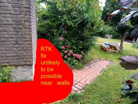
| − | [[File:No_rtk_fix_near_walls.jpg|PCB| | + | [[File:No_rtk_fix_near_walls.jpg|PCB|450px]] |
Some of the environments where we successfully tested RTK GPS: | Some of the environments where we successfully tested RTK GPS: | ||
| Zeile 494: | Zeile 494: | ||
In this section you will upload the Arduino code ('Sunray Firmware') to your Ardumower. (Tip: You can watch below steps in this video (German): https://www.youtube.com/watch?v=vzREteqtzac) | In this section you will upload the Arduino code ('Sunray Firmware') to your Ardumower. (Tip: You can watch below steps in this video (German): https://www.youtube.com/watch?v=vzREteqtzac) | ||
| − | 1. '''Download''' and start Arduino IDE: | + | 1. '''Download''' and start Arduino Legacy IDE (1.8.19): |
https://www.arduino.cc/en/Main/Software | https://www.arduino.cc/en/Main/Software | ||
| Zeile 533: | Zeile 533: | ||
'''NOTE''': You can use the Sunray App using the free license with limited features. After trying out the free version, you can '''purchase a Sunray App basic/pro license here''': http://grauonline.de/cms2/?page_id=3170. (NOTE: I have been working full-time one year on the firmware and App. Please support my work by purchasing a license. Thank you! :-)) | '''NOTE''': You can use the Sunray App using the free license with limited features. After trying out the free version, you can '''purchase a Sunray App basic/pro license here''': http://grauonline.de/cms2/?page_id=3170. (NOTE: I have been working full-time one year on the firmware and App. Please support my work by purchasing a license. Thank you! :-)) | ||
| − | * Click here to download the '''Sunray App | + | * Click here to download the '''Sunray App Manual''': https://drive.google.com/file/d/1NNrUEm2_amfMAjGY7ShcYtixtUgWGnyJ/view?usp=sharing |
* Click here to watch our '''Sunray App Video Tutorial''': https://www.youtube.com/watch?v=iCrBT6e1tw0 | * Click here to watch our '''Sunray App Video Tutorial''': https://www.youtube.com/watch?v=iCrBT6e1tw0 | ||
| Zeile 953: | Zeile 953: | ||
[[File: Sensortest.png|400px]] | [[File: Sensortest.png|400px]] | ||
| − | Obstacle detection and avoidance: For each detected (dynamic) obstacle, the robot firmware will set a temporary (dynamic) obstacle in front of the robot (shown in blue) and compute a new route from the current start position to the current goal position around all static and dynamic obstacles. Once the robot has reached the current goal position, all temporary obstacles are removed. | + | Obstacle detection and avoidance: For each detected (dynamic) obstacle, the robot firmware will set a temporary (dynamic) obstacle in front of the robot (shown in blue) and compute a new route from the current start position to the current goal position around all static and dynamic obstacles. Once the robot has reached the current goal position, all temporary obstacles are removed. NOTE: The robot will not transmit any obstacle data to the app, the given image is just for understanding of the obstacle avoidance. |
| Zeile 1.031: | Zeile 1.031: | ||
Steps to use docking/undocking in the App: | Steps to use docking/undocking in the App: | ||
| − | 1. '''Place the docking station far away (>2m) from larger obstacles like walls etc.'''. | + | 1. '''Place the docking station (indicated by the blue dot) within the mowing area or max. 2m away from the mowing area. Place the docking station far away (>2m) from larger obstacles like walls etc.'''. |
2. '''Record docking points''': Activate '''Record mode: dock''' in the App, then manually steer your robot mower from a position with good sky view (good GPS signal) (first docking point) into the docking station until the docking contacts (last docking point), and add docking points via the App during this process. | 2. '''Record docking points''': Activate '''Record mode: dock''' in the App, then manually steer your robot mower from a position with good sky view (good GPS signal) (first docking point) into the docking station until the docking contacts (last docking point), and add docking points via the App during this process. | ||
Aktuelle Version vom 18. August 2023, 17:03 Uhr
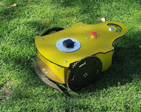
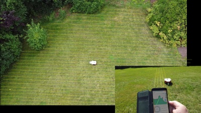
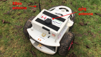
'Mows like on rails...' This is an experimental RTK GPS-based mower that you can build yourself. Ardumower RTK doesn't need a perimeter wire as it uses (cm-precise) RTK GPS.
Key features:
- No perimeter wires (cm-precise GPS)
- Obstacle detection via: ultrasonic, bumper and GPS feedback
- Single mowing unit ground coverage performance (0.4m/s or 1.5km/h, 18cm path offset) : 100 qm per hour / 2400 qm (=0.24 hectare) per day
- Maximum supported ground coverage (by CPU memory) for maps: 600m x 600m (36 hectare)
- Overall power consumption (average) with single mowing unit: 40W (60W peak, 7W idle)
- Single battery (125Wh) run-time (average): 3 hours / double-battery (250Wh): 6 hours
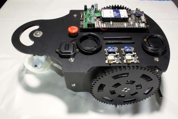
This page describes how to build your own (experimental) RTK-GPS mower. It requires an Ardumower DIY robotic mower system and a RTK-GPS kit. You can get the RTK mower as a whole kit in the shop too (click here to get the RTK mower or just the RTK kit).
This RTK mower project is still in EXPERIMENTAL state! This is a prototype (not more) to explore RTK GPS, to find out if it could be a solution for some backyards (or even some more), to get experiences with this technology, and to finally build a more complete software with it.
Inhaltsverzeichnis
- 1 Videos (Demos/Tutorials)
- 2 What is RTK and what are the requirements (environment and hardware)
- 3 Assembling the chassis and PCB
- 4 Requirements
- 5 Installation steps
- 6 Bluetooth BLE UART module (HM-10)
- 7 Bluetooth BLE/WiFi UART module (ESP32)
- 8 PCB1.4 GPS
- 9 PCB1.3 GPS pin fix and wire fix
- 10 PCB1.3 odometry divider
- 11 Adafruit Grand Central M4
- 12 RTK base
- 13 RTK rover
- 14 Rover configuration (messages)
- 15 Download, Arduino Code, Firmware
- 16 Phone App
- 17 Odometry test
- 18 Position source mode
- 19 Record perimeter and exclusions
- 20 Mowing pattern, pattern angle, mowing offset
- 21 RTK GPS test (invalid, float, fix) and FIX robustness and correctness
- 22 RTK float-to-fix recovery and false-fix issues
- 23 GPS checksum errors
- 24 XBee RF bandwidth/corruption issues
- 25 GPS antenna selection guide
- 26 IMU, sensor fusion
- 27 Ultrasonic sensor
- 28 Bumper sensor
- 29 Extending WiFi range with outdoor access point
- 30 Portable WiFi router for NTRIP
- 31 Charging process, longer battery operation time
- 32 Automatic robot switch off
- 33 Docking
- 34 WiFi module
- 35 Bluetooth Low Energy (BLE) and WiFi external antenna
- 36 What are the differences between the Ardumower and ArduSimple ublox receiver configurations
- 37 Troubleshooting
- 38 How to record GPS data
- 39 Datasheets
- 40 Data privacy
- 41 Discussion / questions / forum thread
- 42 SD card module
- 43 SD card logging
- 44 R/C model
- 45 Hardware debugging
- 46 XBee module configuration
- 47 Firmware Console Debugging
- 48 Further links
Videos (Demos/Tutorials)
 Click below to watch demo and tutorial videos to get an idea what you can do with this RTK system already:
- Intro: Ardumower RTK - What is Ardumower RTK and how does it work?
- Promotion: Ardumower 'mowing with a heart'. For those you love.
- Intro: Waypoints, Mowing, Docking using cm-precise RTK
- Demo: Path planning and mowing demo (showing cm-precise RTK mowing)
- Demo: Docking demo (showing cm-precise RTK in docking station)
- Demo: Dynamic obstacle avoidance demo (using GPS feedback)
- Test: Dynamic obstacle avoidance test (using ultrasonic sensor)
- Test: Testing RTK fix robustness (testing RTK fix robustness near walls, buildings)
- Test: Single GPS receiver test using Internet-based NTRIP client (SAPOS service)
- Test: Challenging environment test - measurement & visualization of float solution error
- Tutorial: How to use the app (German with English subtitles)
- Podcast: Talk between Markus and Alexander about Ardumower RTK (German)
What is RTK and what are the requirements (environment and hardware)
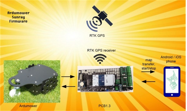
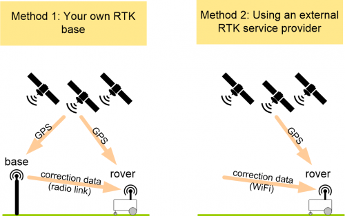
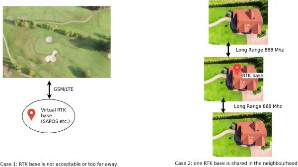
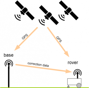
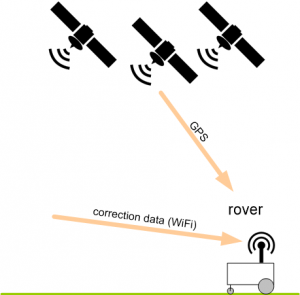
RTK-GPS uses two GPS receivers, one for the reference antenna (base) and one for the robot mower (rover) which both communicate in realtime via radio modules (see image below). The base constantly sends correction data so the rover can compute its cm-precise (relative) position. In the RTK-GPS kit, everything required (receivers, radios, antennas etc.) is included. Also, if you don't want to operate your own RTK base, you can use an external base service via Internet (e.g. like SAPOS in Germany, FLEPOS in the Netherlands, SWEPOS in Sweden, ASG-EUPOS in Poland, and others). This will reduce the hardware cost by about a half. If using your own RTK base, long-range radio modules (e.g. 868 Mhz) are preferred over standard 2.4 Ghz radio modules as they better penetrate buildings, trees etc. NOTE: Using your own RTK base is highly recommended as this will give most robust (RTK fix) position results!
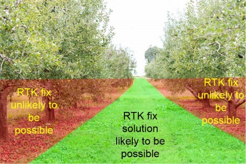
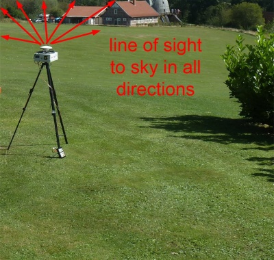
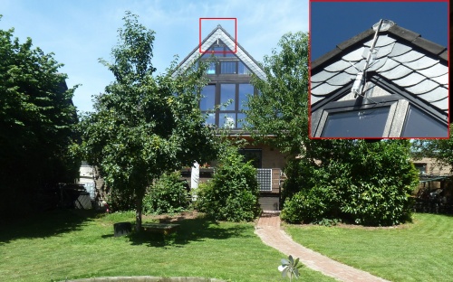
To be able to use RTK-GPS, your robot mower should have a good and open view to the sky at all locations (see photo below). RTK-GPS will NOT work under extreme limited sky view, near walls, in buildings, in narrow areas with larger obstacles all around. There should be at least 15x15m free space on the lawn (without walls and too many trees) to get a robust RTK fix solution on the complete lawn.
Some of the environments where we successfully tested RTK GPS:
 Environment 'AG' (mostly unobstructed sky view)
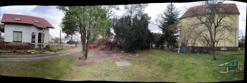 Environment 'ML' (partial obstructed sky view due to large trees on the lawn)
These are the hardware requirements to add RTK-GPS to your Ardumower. You can purchase the required hardware from Marotronics ![]() .
.
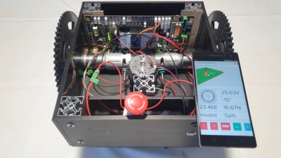
- Ardumower chassis kit using Ardumower motors (incl. odometry) and PCB 1.3/1.4 (incl. Adafruit Grand Central M4/Arduino Due and MC33926 motor drivers)
- RTK kit (it's recommended to purchase the RTK-GPS modules via Marotronics as you get them pre-configured for the Ardumower there)
- ESP32 BLE+WiFi (recommended) or Bluetooth 4.0/BLE UART module (CC2540)
- A smartphone (Android/iOS) for configuration of your Ardumower
Assembling the chassis and PCB
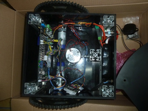
Please follow the steps described at the main page for assembling chassis, motors, docking station etc. and PCB1.3/1.4. After you have assembled the chassis and PCB you can follow the steps below for the RTK functionality.
Requirements
Ardumower Sunray is an alternative Firmware (experimental) for the Ardumower DIY robotic mower system. It uses RTK GPS to localize cm-precise without a perimeter wire.
It requires Ardumower kit mowing and gear motors, PCB1.3/1.4, Adafruit Grand Central M4(or Arduino Due), Ardumower RTK kit, Bluetooth BLE and a phone (Android/iOS).
- Optimized for Ardumower kit mowing and gear motors and PCB 1.3/1.4
- Optimized for Adafruit Grand Central M4 (highly recommended) or Arduino Due
- Optimized for RTK
-
 Incomplete (Sunray is 'work in progress') - all features like docking, GPS signal-loss detection, obstacle detection and avoidance are experimental and features like mowing zones, improved path planning, smart home integration (e.g. MQTT) are going to be added later...
 -
 Experimental: everything you see in the videos is already working but in early prototype phase (never run your Ardumower unattended with this firmware)!
 -
 Only-works-as-a-whole: all software, hardware and motor components are designed and optimized as a whole, if you try to replace or exclude some component not as designed, you risk to damage your hardware with the software
Use Azurit Firmware instead if you need a firmware with more complete features for your Ardumower...
Installation steps
IMPORTANT : Please read ALL sections below when assembling your Ardumower RTK. Some sections are optional, however most of the sections are important. Sections further to the end are related to troubeshooting and typical errors.
Bluetooth BLE UART module (HM-10)
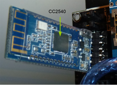
1. Install Bluetooth 4.0/BLE module (range 10m, 8 Kbps) on your Ardumower PCB1.3/1.4 (replace any installed Bluetooth 2.0 module).
IMPORTANT: Verify the pinout of your BLE module is matching your Ardumower PCB pinout (shown at the PCB1.3 back side)!
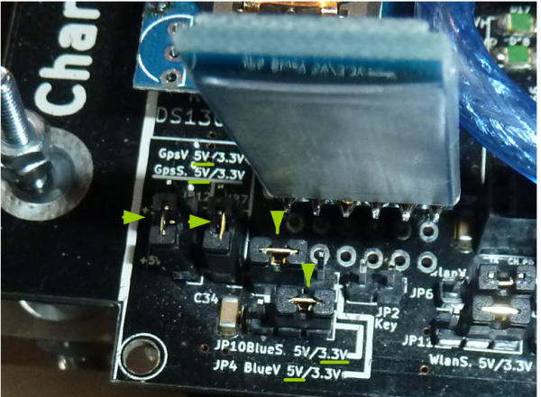
2. Set JP10 (BlueS - Bluetooth signal level) to 3.3V
3. Set JP4 (BlueV - Bluetooth voltage) to 5V
4. Set JP6 (WIFI voltage) to 3.3V
5. Set JP11 (WIFI signal level) to 3.V
NOTE: If your experience Bluetooth module communication issues, have a look at the GPS RX pin fix and perform the same RX pin fix for the Bluetooth RX pin.
You can find a list of working combinations of BLE-module and smartphone on this page: BLE-Module_-_List_of_variants.
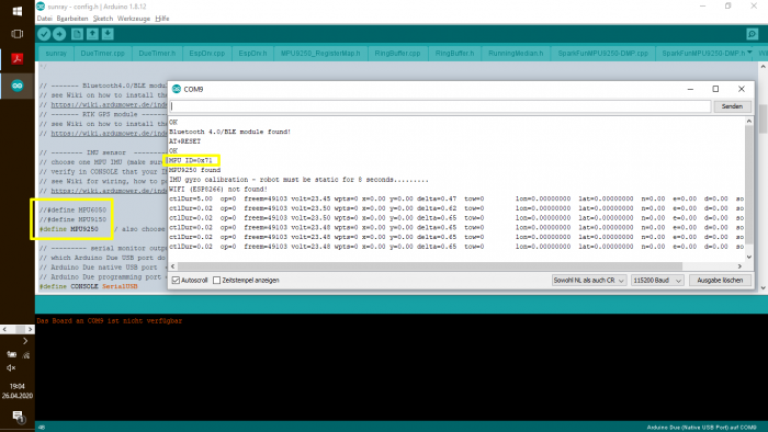
The BLE firmware version of your module is shown in the Arduino IDE serial console at robot boot time:
https://docs.google.com/document/d/14qa15AKLG0EUfNJKfFPwAsKfrLlM0yoqJ1TyiM5c9Fk/edit?usp=sharing
If you have BLE firmware 5.3, the module may not work correctly or stable and it is recommended to use an ESP32 as a BLE+WiFi module (see below)
Bluetooth BLE/WiFi UART module (ESP32)
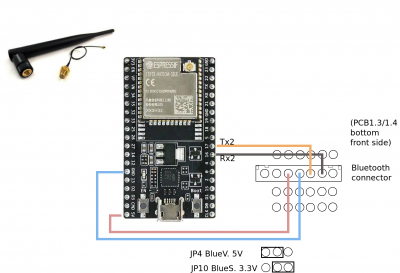
Due to the many issues with latest firmwares (on both BLE HM-10 modules and WiFi ESP8266), we decided to replace both BLE and WiFi modules by a single new module (ESP32). It works by removing any existing BLE and WiFi module and connecting the ESP32 to the PCB1.3/1.4 Bluetooth connector as shown below.
1. Install ESP32 BLE+WiFi on your Ardumower PCB1.3 (replace any installed Bluetooth 2.0 module).
IMPORTANT: Verify the pinout of your BLE module is matching your Ardumower PCB pinout (shown at the PCB1.3 back side)!
2. Set JP10 (BlueS - Bluetooth signal level) to 3.3V
3. Set JP4 (BlueV - Bluetooth voltage) to 5V
4. Download the ESP32 BLE+WiFi firmware and using Arduino IDE, configure your WiFi user+password in the code, and finally install as shown in the screenshots at this link: https://github.com/Ardumower/Sunray/tree/master/esp32_ble
NOTE: If your ESP32 is not available as a device, you may have to install an USB driver: https://www.silabs.com/developers/usb-to-uart-bridge-vcp-drivers
Related topics: Sunray App connection issue solved (forum link)
PCB1.4 GPS
NOTE: Please skip this section for PCB1.3
- Set JP7 (GpsV - GPS voltage) to 5V
- Set JP12 (Gps_S - GPS signal level) to 3.3V
PCB1.3 GPS pin fix and wire fix
NOTE: Please skip this section for PCB1.4
Set JP7 (GpsV - GPS voltage) to 5V (please ignore the others jumpers, we will configure them further below)
IMPORTANT: Actually, there are required two GPS fixes (step 1 and step 2 - see below), so both GPS_RX and GPS_TX can work!
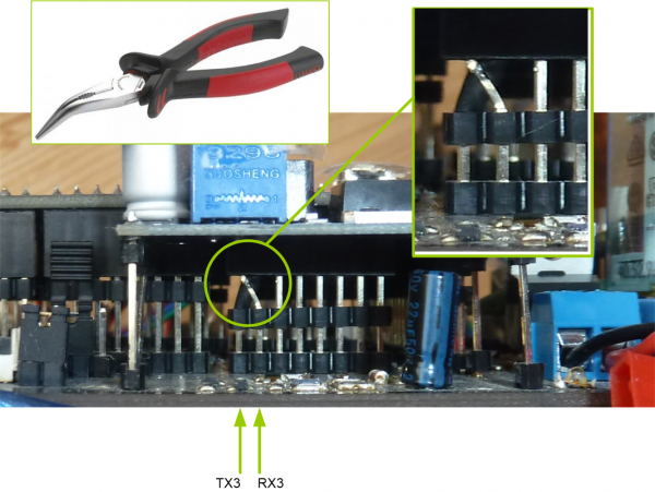
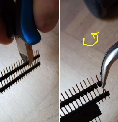
Step 1: Swapping pins (only PCB1.3)
The pins TX3 and RX3 are incorrectly routed on PCB1.3 - Fix it by swapping the TX3 and RX3 pin headers as shown below.
You can see the fixing process in this video: https://youtu.be/T-EqU5azCAU?t=140
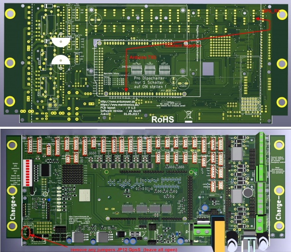
Step 2: Fixing GPS_RX pin ('GPS wire fix') (only PCB1.3)
P5 GPS_RX is not working as expected on PCB1.3. Fix it with these steps:
- Directly connect P5 GPS_RX and Arduino TX3 using a wire at the PCB backside as shown below.
- Remove jumper Gps_S (JP12)
- IMPORTANT: On the rover GPS module, connect simpleRTK2B IOREF to simpleRTK2B 3V3_OUT (to choose signal voltage level 3.3v).
PCB1.3 odometry divider
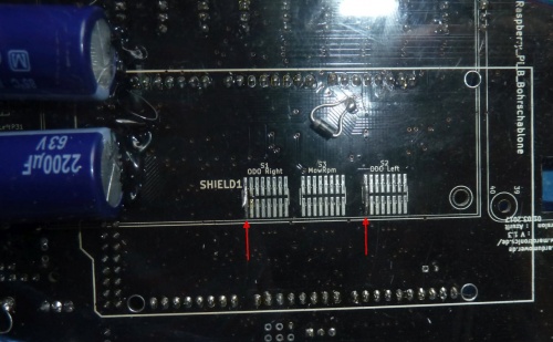
The PCB1.3 odometry divider for the left and right motors should be configured as follows (NOTE: no need to change the mower divider, you can keep your existing mower divider configuration):
Adafruit Grand Central M4
Using the new Adafruit Grand Central M4 instead of Arduino Due is highly recommended as it has more working memory (RAM) for maps and a floating point unit for faster computations.
Installations steps:
1) Add 2.2K/activate resistors (aka 'I2C pull-up') to the Adafruit Grand Central M4 board as shown below, depending on you Board-Version (PCB 1.3 vs. PCB 1.4). NOTE: If the pullups are missing, the Ardumower Sunray firmware will hang at boot time and nothing will be displayed on serial console output!
| PCB 1.3 | PCB 1.4 |
|---|---|
Add external resistors (2k2 Ohm) on Grand Central M4. 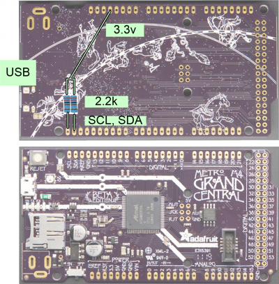
|
Bridge the two marked jumpers on PCB 1.4. 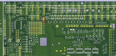
|
2) Disable Ardumower PCB1.x jumper JP13 (deactivate Arduino Due clone reset circuit).
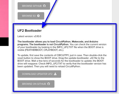
3) It is highly recommended to upgrade the bootloader on the Adafruit Grand Central M4 board. Download the the latest bootloader file here (look at the bottom of this link for .UF2 bootloader file): https://circuitpython.org/board/grandcentral_m4_express/
4) Connect the Adafruit Grand Central M4 via USB to your computer.
5) Press the RESET button on the Adafruit Grand Central M4 twice, the larger LED on the Adafruit Grand Central will become GREEN, and a new drive will appear in Windows Explorer/Mac Finder ('GCMBOOT').
6) Copy the .UF2 bootloader file to the Adafruit Grand Central M4 drive ('GCMBOOT') - the drive will disappear and after 10 seconds the drive will appear again. The bootloader upgrade has finished (Alternative instructions here: https://learn.adafruit.com/adafruit-grand-central/update-the-uf2-bootloader).
7) Follow the instructions here to add 'Adafruit Grand Central M4' support to the Arduino IDE by installing both Arduino SAMD boards and Adafruit SAMD boards packages : https://learn.adafruit.com/adafruit-grand-central/setup
RTK base
Method 1: Your own RTK base
This is the recommended installation method as it also will give you RTK fix solution results in cloudy weather conditions. Your own RTK base should be located max. 8 km away from your mowing area. The GPS antenna should have a clear sky view and is ideally mounted at a high (and steady) position. Using long-range (LR) wireless radio-frequency (RF) modules, the GPS correction signal is transmitted to the robot (it's a one way transmission). Multiple robots can be operated by a single RTK base. Using long-range radio modules (e.g. 868 Mhz) is preferred over standard 2.4 Ghz radio modules as they better penetrate buildings, trees etc.
WARNING: Handle your GPS modules with care, it is an expensive piece of hardware. If you have any doubt, or if you are unsure, please ask in the Ardumower forum for help.
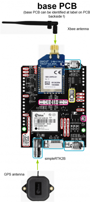
1. Make sure you have the simpleRTK2B module marked as 'BASE' in your hands (look at simpleRTK2B PCB label at backside!)
2. Connect Xbee LongRange dipole antenna
3. Connect GPS multifrequency patch antenna. NOTE: antenna cable is very sensitive, never bend the antenna cable! Minimum bend radius: 5cm!
4. Connect a USB 5v power supply to the USB port marked as 'POWER+GPS'
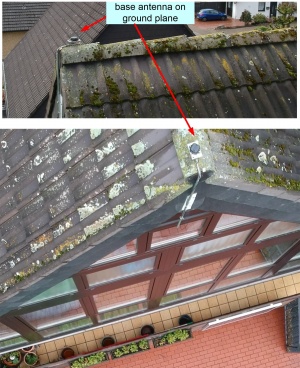
5. Install the GPS base antenna - it should have clear view to the sky in all directions without any obstacles. For best results install GPS antenna on the roof. Alternatively, if you have an open area (without trees and other obstacles), you can install the base antenna on a tripod.
NOTE: The robot mower will get and save all position coordinates relative to the base antenna (East, North) - do not move the base antenna after recording the virtual perimeter with the phone app.
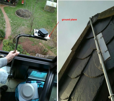
6. Improving position solution robustness: for robust position solutions (FIX), you will need to install a (conductive) ground plane (10x10cm, make it round if possible) for the patch antenna. Install the patch antenna on top of it like shown below. This will give you most robust position results.
7. Download ublox u-Center v21.05, install it and start it: Download link
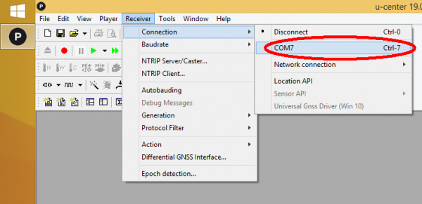
8. Choose 'Receiver->Connection' and choose your base module COM port. NOTE: If you cannot see a COM port, you may have to install ublox VCP driver (and/or choose the serial driver for the detected GNNS device in Windows device manager).
9. Choose 'View->Configuration View'. Choose configuration message 'TMOD3(Time mode 3)' and choose:
- Mode '1 - Survey-In' (90s/5m precision) if you use 'relative coordinates' in the App (recommended). It's ok to choose such a worse precision as this is related to absolute GPS world coordinates only and we don't use this (unprecise) absolute world coordinate when using (cm-precise) relative base coordinates.
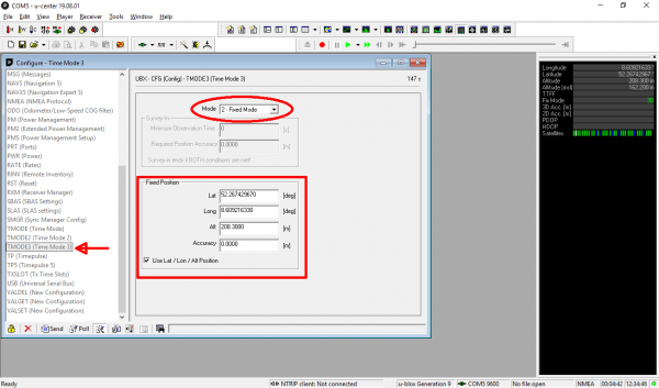
- Mode '2 - Fixed Mode' if you used 'absolute coordinates' in the App (not recommended). Enter your base coordinates as shown in the image. NOTE: You can find out your precise bases coordinates using the 'Survey-In' mode which will take several hours to get down to a precise position. NOTE: You can run the survey-in and compare the GPS solution coordinates (latitude and longitude) from hour to hour. If they do not change anymore, your base coordinates are precise.
10. Click on 'Send'. Your base should get a '3D' position solution (verify this!).
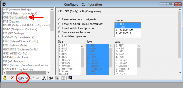
10. From the u-Center menu, choose 'View->Configuration', choose configuration message 'CFG (Configuration)' and click on 'Send' to make the configuration in the base persistent when the rover module is powered off. Do not forget to save the configuration (Receiver -> Action -> Save Config).
11. Tip if using multiple XBee LR kits (base and rover pairs) within a 10km area: The XBee LR kits are all configured with the same network ID. So if one rover is in the range of two base stations, there's going to be cross talk and the rovers will start doing funny things. For the XLR kits are configured with a unique ID per kit, to avoid the situation. Nevertheless the LR kits only really work with line of sight, if the base station antenna is not mounted in the top of the house and can see all the neighbourhood, is quite unlikely that the arrive more far than a couple of houses away.
You have 2 options to solve this problem:
- Configure each pair in unicast mode so each base station only talks to specified rover.
- Change the network ID for each pair (PAN ID).
These can be done with the tool Digi XCTU.
Method 2: Using an RTK external base service (Internet-based)
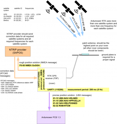
This section describes how to use an external Internet-based correction service (NTRIP, e.g. SAPOS in Germany, FLEPOS in the Netherlands, SWEPOS in Sweden, ASG-EUPOS in Poland, and others) instead of your own base station. You can reduce cost with this method because you don't need an RTK base PCB. Instead you will require the WiFi NTRIP Master module for your rover PCB from Marotronics. Follow these steps for the rover PCB:
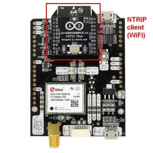
1. Instead of the XBee module install the WiFi NTRIP Master module on your rover PCB as shown in above photo.
2. Use your smartphone or laptop to connect to the WiFi network that the module created, with name “ESP_XBee_XXXXXX” where XXXXXX is a random number.
3. Go to your browser and type the following address “192.168.4.1”, a web interface will appear.
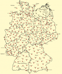
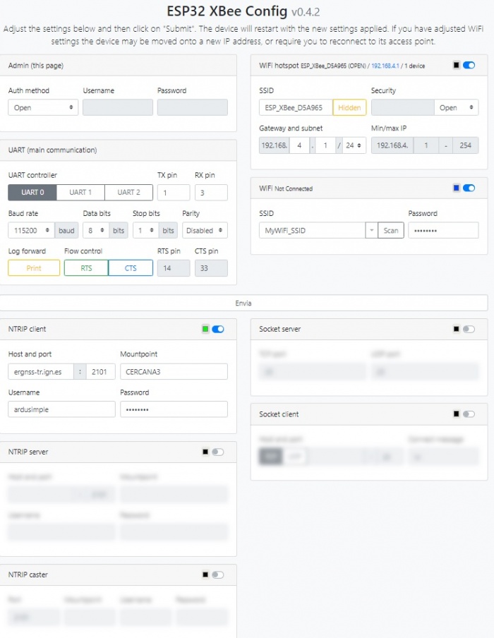
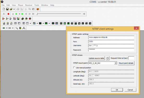
4. Configure your preferred NTRIP service provider (host, port, mountpoint, username, password), and through which WiFi network should it connect to internet. Example NTRIP mount points (Germany SAPOS service generating virtual reference station):
 Nordrhein Westfalen (SAPOS HEPS): VRS_3_4G_NW
 Niedersachsen       (SAPOS HEPS): VRS_3_2G_NI
 Berlin              (SAPOS HEPS): VRS_3_2G_BE
 Baden Württemberg   (SAPOS HEPS): VRS_3_3G_BW
Additionally, you can find out more NTRIP casters here:
- http://www.epncb.oma.be/_networkdata/stationmaps.php
- https://igs.bkg.bund.de/dataandproducts/streams
5. Use UART0 and 115200 baud for the connection to the ublox GPS receiver (rover).
6. Save configuration and reset the system. From now on, every time the WiFi router you configured is in range, the WiFi NTRIP Master will connect autonomously and provide RTK corrections to your rover PCB (If you ever experience any problems and are unable to connect to the NTRIP master device, you can hold the NTRIP master BOOT button for 5 seconds and the ESP32 will be reset to its default configuration). Verify that your XBee-Wifi-module is successfully connected to the Internet by typing the configured XBee IP address in your browser!
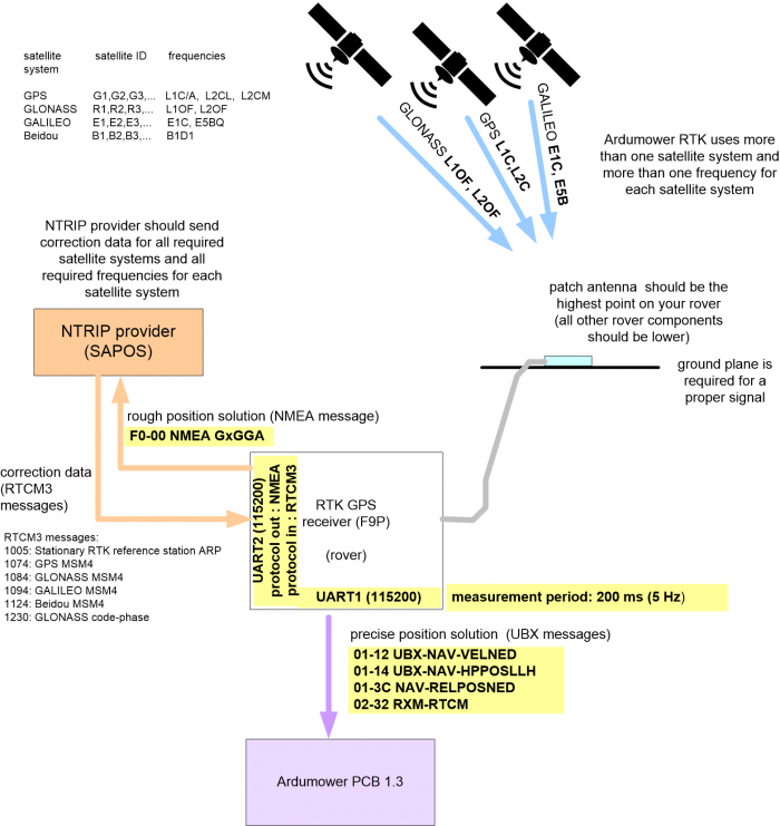
7. Connect the rover PCB via USB to your PC, and make sure NMEA protocol out is activated for UART2 out at 115'200bps (configuration view-> message 'PRT (Ports)'). Also make sure NMEA GGA message is active with rate 60 on UART2 (configuration view->message 'MSG (Messages)'->F0-00 NMEA GxGGA). Some NTRIP service providers need this NMEA message to compute a virtual base station (VRS) based on the initial estimated GPS fix position. Verify that the LED GPS-XBEE starts to blink which means the GPS receiver is sending the (rough) GPS position to the XBee module!
8. Finally, verify the LED 'XBEE-GPS' is blinking (the rover receives correction data) and the correction age (seconds) shown near the fix solution in the phone app is not increasing. If it does NOT work:
- Verify you have properly configured the rover module (see further below)
- Verify your NTRIP client connection data via ucenter (see further below)
- Activate NTRIP module console output (log forward print), connect GPS rover module via the 2nd USB port (near the NTRIP module) to your PC and start Arduino IDE serial console to monitor the console output
9. If your NTRIP base antenna position is not constant, you have to switch to position source mode 'absolute' in the App (see section App for more details).
How can I find out if my NTRIP provider (e.g. SAPOS) properly works and supports the required correction messages
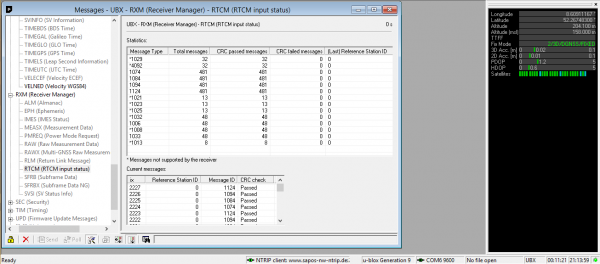
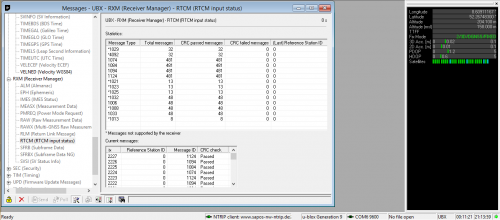
You can verify the received correction messages (RTCM3) for the individual satellite systems (GPS, GLONASS, etc.) via ublox uCenter. Start the NTRIP client via 'Receiver->NTRIP client...'
...and then display the received RTCM3 messages via 'View->Messages View->UBX->RXM->RTCM':
These are the RTCM3.3 messages you should see and may see ( * means not supported by F9P receivers , --> means this message should be activated when using your own F9P RTK base station):
    1001: L1-only RTK observables
    1002: Extended L1-only RTK observables
    1003: Compact L1&L2 observables
    1004: Extended L1&L2 observables
--> 1005: Stationary RTK reference station ARP
    1006: Stationary RTK reference station ARP with height
    1007: Antenna descriptor
    *1008: Antenna descriptor and serial number
    1009: L1-only GLONASS observables
    1010: Extended L1-only GLONASS observables
    1011: GLONASS basic RTK L1&L2
    1012: GLONASS extended RTK L1&L2
    *1013: System parameters
    *1019: GPS ephemeris data
    *1020: GLONASS ephemeris data
    *1021: Helmert/Abridged Molodenski Transformation Parameters
    *1023: Residuals, Ellipoidal Grid Representation
    *1025: Projection Parameters, Projection Types other than Lambert Conic Conformal
    *1032: Physical Reference Station Position
    1033: Receiver and antenna descriptors
    *1073: GPS MSM3
    *1083: GLONASS MSM3
    *1093: GALILEO MSM3
    *1123: Beidou MSM3
--> 1074: GPS MSM4
--> 1084: GLONASS MSM4
--> 1094: GALILEO MSM4
--> 1124: Beidou MSM4
    1075: GPS MSM5
    1085: GLONASS MSM5
    1095: GALILEO MSM5
    1125: Beidou MSM5
    1077: GPS MSM7
    1087: GLONASS MSM7
    1097: GALILEO MSM7
    1127: Beidou MSM7
--> 1230: GLONASS code-phase (this message could be missing - then 1033 should be received instead!)
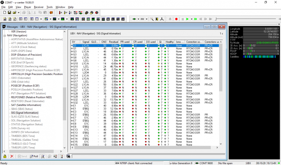
You can verify the satellite frequencies via 'View->Messages View->UBX->NAV->SIG':
These are the frequencies you should see for each satellite system:
    GPS         G1,G2,G3,...   L1C/A
                               L2CL
                               L2CM
    GLONASS     R1,R2,R3,...   L1OF
                               L2OF
    GALILEO     E1,E2,E3,...   E1C
                               E5BQ
    Beidou      B1,B2,B3,...   B1D1
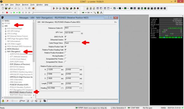
And finally, you should see a carrier solution 'float' or 'fix' for a RTK solution:
RTK rover
WARNING: Handle your GPS modules with care, it is an expensive piece of hardware. If you have any doubt, or if you are unsure, please ask in the Ardumower forum for help.
Make sure you have configured the Ardumower PCB (1.3/1.4) GPS jumpers as shown in the Ardumower PCB GPS section above correctly.
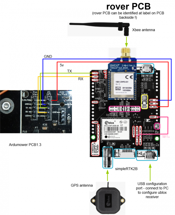
1. Make sure you have the simpleRTK2B module marked as 'ROVER' in your hands (look at simpleRTK2B PCB label at backside!)
2. Connect XBee LongRange dipole antenna
3. Connect GPS multifrequency patch antenna. NOTE: antenna cable is very sensitive, never bend the antenna cable! Minimum bend radius: 5cm!
4. Connect PCB1.3_GPS_GND to simpleRTK2B GND
5. Connect PCB1.3_GPS_5V to simpleRTK2B 5V_IN
6. Connect PCB1.3_GPS_TX to simpleRTK2B TX1
7. Connect PCB1.3_GPS_RX to simpleRTK2B RX1
8. IMPORTANT: Connect simpleRTK2B IOREF to simpleRTK2B 3V3_OUT (to choose signal voltage level 3.3v)
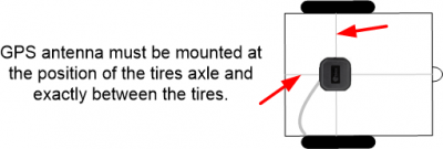
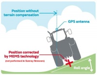
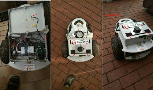
9. Install XBee antenna and GPS antenna on the Ardumower. The GPS antenna must be mounted at the point where the robot rotates around (aka the 'control point'). For a 2 differential wheel robot, this position is at the tire axle and between both tires. Do not mount the GPS antenna too high because when there's slope the higher position of the antenna is not the same as the position of the robot (see example with slope below):
10. Improving position solution robustness: for robust position solutions (FIX), you will need to install a (conductive) ground plane (10x10cm, make it round if possible) for the patch antenna. Place the patch antenna on top of it like shown below. This will get you most robust position results. Note: you do not have to ground the ground plane as the contact to antenna is capacitive.
More details about ground planes for patch antennas can be found in the u-blox GNSS Antennas Application note (UBX-15030289) and in ublox Multi-band, high precision GNSS antennas (ANN-MB series).
Rover configuration (messages)
![]() NOTE: below steps for rover configuration using u-center software are no longer necessary - the Sunray firmware will automatically configure your ublox f9p GPS module (rover) when started - please skip this section (and ensure you have done the GPS fix step 2).
NOTE: below steps for rover configuration using u-center software are no longer necessary - the Sunray firmware will automatically configure your ublox f9p GPS module (rover) when started - please skip this section (and ensure you have done the GPS fix step 2).
![]() WARNING: Only apply the steps below for the ROVER module - not for the BASE module!!
WARNING: Only apply the steps below for the ROVER module - not for the BASE module!!
NOTE: If you purchased your RTK-GPS modules at Marotronics, these modules should be pre-configured and you can skip this section.
1. IMPORTANT: Make sure the Ardumower is turned off!
2. Connect SimpleRTK ROVER module USB port marked as 'POWER+GPS' to your PC.
3. Download ublox u-Center v21.05, install it and start it: Download link
4. Choose 'Receiver->Connection' and choose your rover module COM port. NOTE: If you cannot see a COM port, you may have to install ublox VCP driver (and/or choose the serial driver for the detected GNNS device in Windows device manager).
--Method 1 (Using a configuration file - recommended)--
5. Download the ublox rover configuration file (you can find it in the folder 'ublox_f9p_configs'): https://github.com/Ardumower/Sunray/archive/master.zip
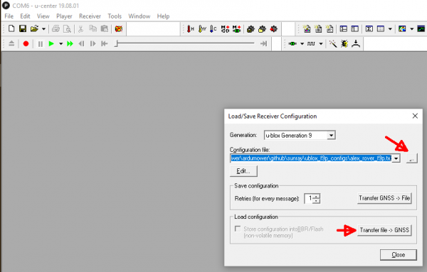
6. Using ublox u-Center, upload the configuration file to your ublox receiver (rover). Choose 'Tools->Receiver Configuration...', choose the config file and then transfer it to the GPS receiver.
After your ublox receiver has been configured, go to point 9 to permanenlty save the configuration in the GPS receiver.
--Method 2 (Without configuration file)--
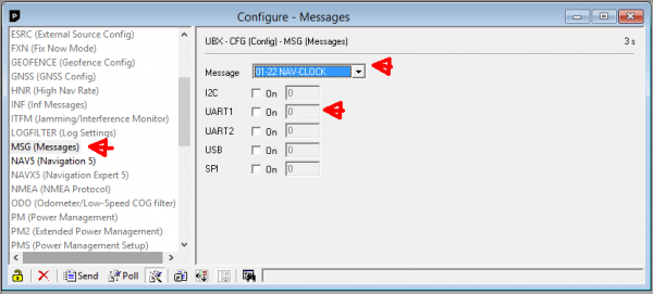
5. In this step we want to turn off all broadcast messages except one. Choose 'View->Configuration View'. Choose configuration message 'MSG (Messages)' and select one message after the other in the list (0A-37 MON-HW3, 0A-09 MON-HW, ..., etc.). For each message, make sure the selected message is turned off for UART1 and UART2. Example for message '01-22 NAV-CLOCK' that has been deactivated for UART1:
Repeat this step for all messages in the listbox and turn off all messages for UART1 and UART2.
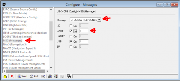
6. Activate the following messages and rates for UART1 and USB:
01-07 UBX-NAV-PVT         10
01-12 UBX-NAV-VELNED      1
01-14 UBX-NAV-HPPOSLLH    1
01-3C NAV-RELPOSNED       1
01-43 NAV-SIG             10
02-32 RXM-RTCM            5
7. Activate the following message and rate for UART1 and UART2 and USB:
F0-00 F0-00 NMEA GxGGA 60
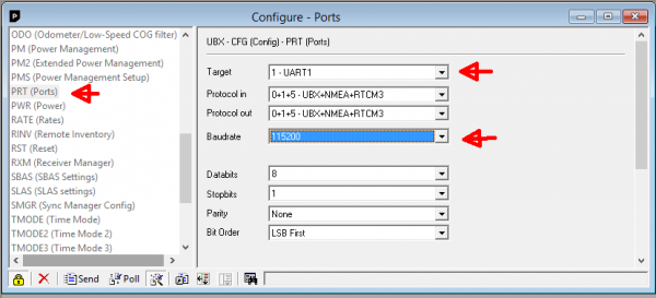
8. Choose configuration message 'PRT (Ports)', choose 'UART1', and set baudrate to 115200 for UART1:
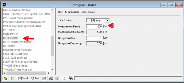
9. Choose configuration message 'RATE (Rates)' and set measurement period to 200ms (5 Hz):
10. From the u-Center menu, choose 'View->Configuration', choose configuration message 'CFG (Configuration)' and click on 'Send' to make the configuration in the rover persistent when the rover module is powered off.
11. Verify that the configuration is actually persistent in the rover module - disconnect the rover module and reconnect. Then go through all previous steps and verify that the configuration is still present.
12. IMPORTANT: Disconnect USB cable from rover module!
Download, Arduino Code, Firmware
In this section you will upload the Arduino code ('Sunray Firmware') to your Ardumower. (Tip: You can watch below steps in this video (German): https://www.youtube.com/watch?v=vzREteqtzac)
1. Download and start Arduino Legacy IDE (1.8.19): https://www.arduino.cc/en/Main/Software
2. Download Ardumower Sunray Firmware release and unzip it: https://github.com/Ardumower/Sunray/releases
(NOTE: the Github 'master' branch may contain a newer but unstable version: https://github.com/Ardumower/Sunray/archive/refs/heads/master.zip)
3. Open the Arduino sketch 'sunray\sunray.ino'.
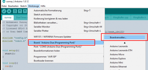
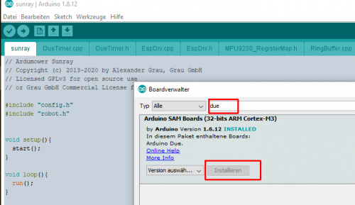
4.1 For Arduino Due: In Arduino IDE, choose 'Tools->Board->Manage' and enter 'Due'. Install the 'Arduino SAM Boards'
4.2 For Adafruit Grand Central M4: Follow the instructions here to add 'Adafruit Grand Central M4' support to the Arduino IDE by installing both Arduino SAMD boards and Adafruit SAMD boards packages : https://learn.adafruit.com/adafruit-grand-central/setup
NOTE: If you get compilation errors with Adafruit Grand Central M4, you may have to downgrade 'Adafruit SAMD Boards' to version to 1.7.5.
5. Start your Ardumower (via the PCB1.3 button P20).
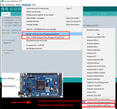
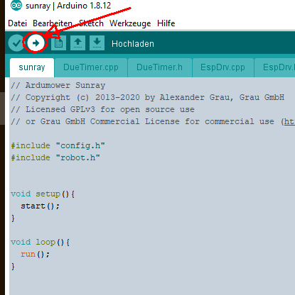
6. Connect Arduino Due USB native port (or Adafruit USB port) to your Computer's USB port. In the Arduino IDE, choose the correct board and port and Upload the sketch to your Arduino Due/Adafruit Grand Central on the Ardumower PCB1.3. After a short while you should hear a 'beep'. Ardumower is now ready for your commands!
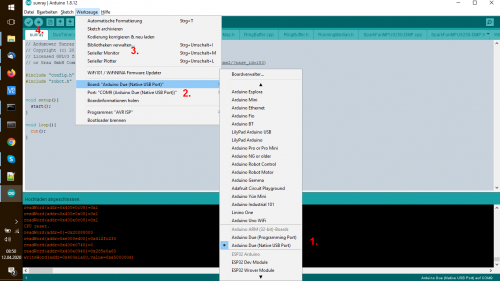
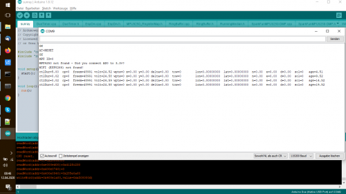
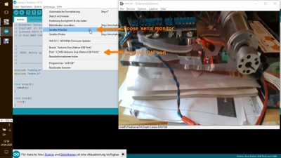
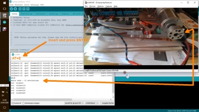
7. If you experience problems (e.g. phone cannot connect to your Bluetooth module), it is recommended to view the serial console of the Ardumower. Connect the Arduino Due via the USB port labeled 'native' to your PC. Choose board 'Arduino Due native USB port' in the Arduino IDE and choose the available Due native COM port. Then choose 'serial monitor' to see the console. Finally choose upload. After uploading, the output on the console should appear and should look like below. The lines 'OK', 'AT+RESET', 'OK' indicate that the Bluetooth module was found. Also, if your Bluetooth module is not listed in the App,ensure that you give the App Bluetooth permissions.
For more details about the console debugging, see:
https://docs.google.com/document/d/14qa15AKLG0EUfNJKfFPwAsKfrLlM0yoqJ1TyiM5c9Fk/edit?usp=sharing
Phone App
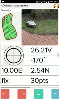
NOTE: You can use the Sunray App using the free license with limited features. After trying out the free version, you can purchase a Sunray App basic/pro license here: http://grauonline.de/cms2/?page_id=3170. (NOTE: I have been working full-time one year on the firmware and App. Please support my work by purchasing a license. Thank you! :-))
- Click here to download the Sunray App Manual: https://drive.google.com/file/d/1NNrUEm2_amfMAjGY7ShcYtixtUgWGnyJ/view?usp=sharing
- Click here to watch our Sunray App Video Tutorial: https://www.youtube.com/watch?v=iCrBT6e1tw0
In this section you will download the App to your phone (Android or iOS) which is used to configure the maps for your mower.
Using the phone app, you can:
- manually steer the mower
- record the virtual perimeter and exclusions
- calculate the waypoints for the mower
- start/stop the mower
NOTE: all maps will be stored on the phone - however maps can be shared and then imported on other devices.
NOTE: The robot mower will work with position coordinates relative to the base antenna (East, North) - do not move the base antenna after recording the virtual perimeter.
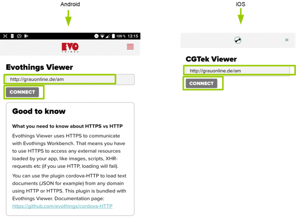
1. Download Viewer App:
  For Android, download Evothings Viewer: https://play.google.com/store/apps/details?id=com.evothings.evothingsviewer
  For iOS, download CGTek Viewer: https://apps.apple.com/de/app/cgtek-viewer/id1135118284
2. Start App and enter the connection URL as shown below and press 'Connect' (NOTE: you will need an Internet connection each time starting the App - once the App is started, no Internet connection is required anymore):
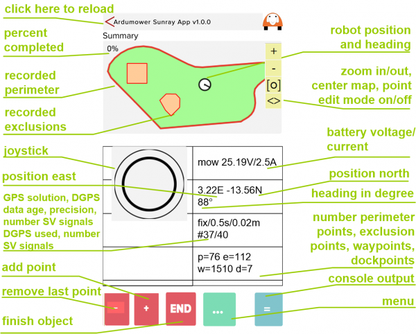
3. The App should start as shown below:
| idle | Robot is stopped. |
| mow | Robot is mowing. After reaching a waypoint, the last sensor error is cleared. |
| dock | Robot is docking. |
| charge | Robot is charging. |
| invalid | no DGPS solution was found |
| float | DGPS solution was found but it is ambiguous and therefore not precise (average error ~20cm). |
| fix | DGPS solution was found and it is cm-precise - position is tracked in realtime (RTK) |
| age | The age (in seconds) of the DGPS correction data sent from base |
Odometry test
Before connecting GPS, verify the odometry of your motors! If you are unable to smoothly steer the robot via the App manually, this will probably fix it!
Both, the robot's motor odometry and GPS-RTK are used to localize the robot. Therefore, it is important to verify that the odometry is working correctly as shown below.
- Make sure IMU and GPS are not connected
- Make sure the robots tires can move freely in the air
- Start Arduino IDE, choose the UART port (Tools->Port from the menu)
- Choose Tools->Serial Monitor from the menu, and send 'AT+E' (ENTER) to the robot (115200 baud). The motor test will start and both motors will rotate 10 times.
Motor test video link: https://drive.google.com/open?id=1ejT8j1Ioq8bDpk3RmWuki5KqI9K1Jq9h
In this motor test, both gear motors will rotate approx. 10 times. If they rotate 12 or 8 times you will have to adjust the odometry settings in config.h.
Finally, the motors should be manually controllable very smoothly as seen in this video: https://youtu.be/fHSolQ5oQfA?t=136
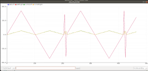
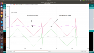
Additionally, there is a motor plot for odometry signal quality diagnostics (including mower motor).
- Make sure the robots tires and the mower motor can move freely in the air (see photo below)
- Start Arduino IDE, choose the UART port (Tools->Port from the menu)
- Choose Tools->Serial Monitor from the menu, and send 'AT+Q' (ENTER) to the robot (115200 baud). The motor plot will start and motor PWM and odometry signal quality will be plotted for a short moment:
Further odometry hardware trouble-shooting (how to measure odometry hardware faults): https://forum.ardumower.de/threads/antriebsmotoren-brushless-pl%C3%B6tzlich-im-schneckentempo.24822/post-54494
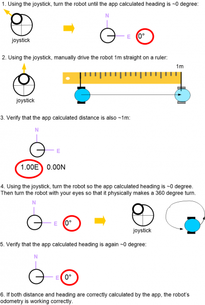
Additionally, you can verify the correct odometry configuration via the App. Start the phone app and follow the steps below to verify that your mower odometry is configured correctly. For this test, make sure that your RTK is turned off (e.g. RTK base module is turned OFF)!
Fixing motor directions (forward/backwards/left/right):
- To make one motor turn in the opposite direction you swap the red (+) and black (-) wires of that motor.
- If (after fixing the motor directions) robot turns into wrong side (left instead of right and vice versa), you swap the left and right motor (and odometry) connections (left motor becomes right motor and vice versa). After swapping left and right motor connections, you fix the turning direction again (1.)
So you will do to a combination of 1. and 2. to get it correctly.
Interpretation of the robot symbol within the App:
- The black line marker inside the white robot circle symbol marks the robot front side. So, the marker always points to the direction the robot would move if steering forward.
- The steering control (virtual joystick) works like this: touching up is forward and touching down is backwards.
Position source mode
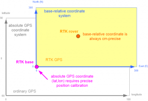
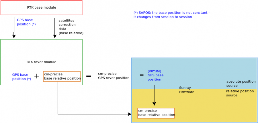
RTK: DGPS can solve the precision problem between a fixed base and a moving rover. However, it cannot compute absolute GPS coordinates (latitude/longitude) precisely. To be able to compute absolute GPS coordinates for a moving rover, you have to know the absolute coordinates of the base. Then the rover can add the precise relative measurements to the absolute base coordinate to compute a precise GPS coordinate.
The ublox GPS receiver sends two positions to the Ardumower:
a) one base-relative position (east/north) in meters (this is used in relative mode)- because virtual base station
   (VRS) coordinates move each start, this mode cannot be used for SAPOS/VRS
b) one absolute latitude/longitude position (this is used in absolute mode and the base coordinate set in the app is always
   substracted from this to calculate again east/north in meters)
To save memory, the rover will always use relative coordinates for the map etc. The map origin (0,0) for the maps can be choosen in the App. WARNING: The relative coordinates cannot be larger than +/-300m. You have to ensure that the map origin (0,0) is not further away than 300m from all recorded points in your map.
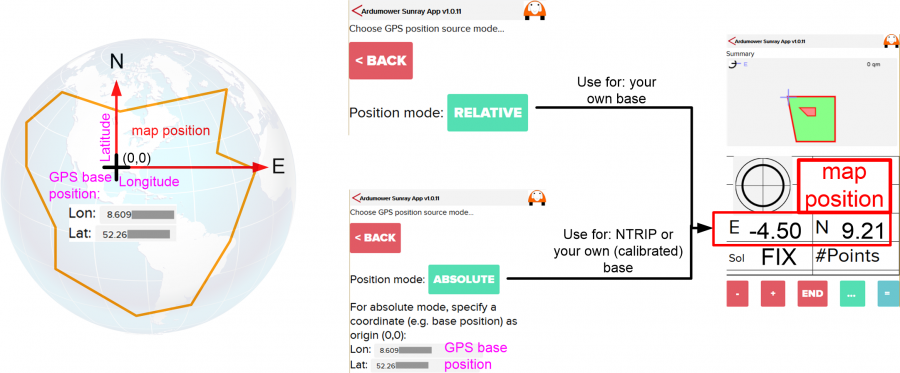
In the App (menu 'Position mode'), you can choose between those two position source modes:
relative: the rover coordinates are always relative to the base antenna  (recommended - use this when using your own base) - if the base
          moves after a map recording, you have to switch to absolute mode
absolute: the rover coordinates are computed as relative to some specified (e.g. your base antennna or house)
          world coordinate (see image below - use this when using an NTRIP client or for a different base position)
Tip: You can use Google Maps to find out (Lon, Lat) coordinates for your location and use them as coordinate (lon,lat) for your base station to set up the absolute position mode: https://www.latlong.net/
Moving a recorded map
If you have recorded your map with the App and need to move it (e.g. due to a position change of your base or because you changed from NTRIP to your own base), you can do this via the absolute position mode and changing (and fine-tuning) the map origin:
- Your base position must have been cm-precisely calibrated (e.g. via ublox u-center Survey-in method)
- Activate the absolute position mode in the App
- Use the coordinate (lon, lat) of your base at the time of your map recording as the map origin. If you used NTRIP for map recording, keep the map origin coordinate you did use for recording.
- Verify the map on the ground with your robot (e.g. a known point like the docking station point).
- If the map points do not match exactly, you can fine-tune them by adjusting (trial-and-error) the last digits of the map origin (lon, lat) in the App
Record perimeter and exclusions
Please watch this help video on how to record perimeter and exclusions:
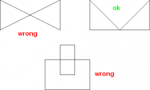
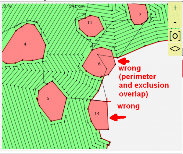
When recording perimeter and exclusions make sure that your perimeter polygon and each of your exclusion polygons do not overlap itself and other polygons.
Example of one polygon overlapping itself and one polygon overlapping another polygon (not allowed):
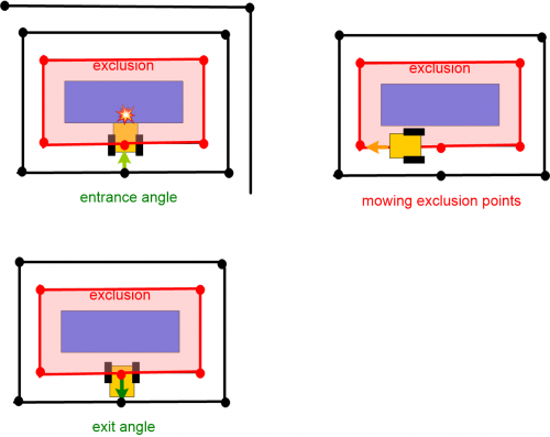
Also, when recording your exclusions, make sure there is enough space around obstacles for entry and exit points where the mower needs to rotate!
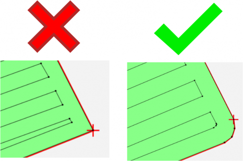
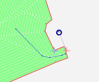
Important: Ensure that you record no 90 degree corners but instead approximate it with smaller changes in angles. This will make your robot turning actions smaller:
Mowing pattern, pattern angle, mowing offset
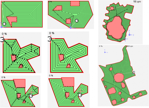
Click here for video demonstration of patterns, pattern angle and mowing offset
Example maps:
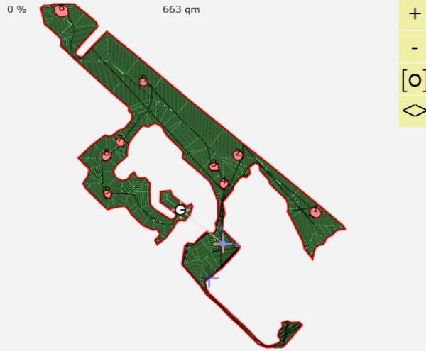
Tip: If you encounter path errors in the calculation, try to move the robot to another area (another position) and then recalculate the waypoints.
RTK GPS test (invalid, float, fix) and FIX robustness and correctness
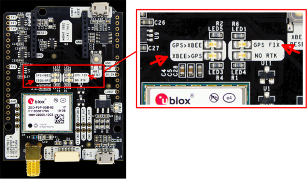
The base and rover LEDs can be used for trouble-shooting. Verify that the LEDs are acting as described below.
The base and rover LEDs should be as follows:
| GPS>XBEE | should blink - your base module is sending satellite reference data to your rover module (via the XBee module) |
| XBEE>GPS | should be OFF - your base module should not receive any XBee/reference signal |
| GPS FIX | should blink - your base module has found a valid GPS signal |
| NO RTK | should be ON - your base module is not performing RTK (real time kinematic) |
| GPS>XBEE | should be OFF - your rover module should not send any XBee signal |
| XBEE>GPS | should blink - your rover module is receiving satellite reference data from your base module (via the XBee module) |
| GPS FIX | should blink - your rover module has found a valid GPS signal |
| NO RTK | should be OFF - your rover module has found a RTK FLOAT (blinking) or FIX (OFF) and is performing real-time kinematic |
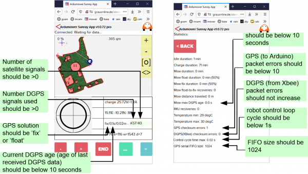
GPS status in the App:
GPS precision test using the App: Click here for video: How to test GPS precision
Fix robustness
Depending on the robot's location (e.g. near trees), it may take some time to get a RTK FIX solution. Also, it appears this RTK FIX can get lost quickly in the first minutes (e.g. near trees). However, after several minutes running time, the RTK FIX is more robust (even near trees). So, for best position results, let the GPS 'warm-up' some minutes at a location with good sky view.
Fix correctness
![]() NOTE: If you power-on the receiver (mower) at limited sky view, the receiver may get a RTK FIX solution but this FIX may be incorrect (and all following data is offset by this incorrect start position!). Therefore it is recommended to always power-on the receiver (mower) at a position with good sky view and to always power-on at the same position!
NOTE: If you power-on the receiver (mower) at limited sky view, the receiver may get a RTK FIX solution but this FIX may be incorrect (and all following data is offset by this incorrect start position!). Therefore it is recommended to always power-on the receiver (mower) at a position with good sky view and to always power-on at the same position!
RTK float-to-fix recovery and false-fix issues
The described GPS filter below is now configured automatically in the Sunray firmware. Please skip this section.
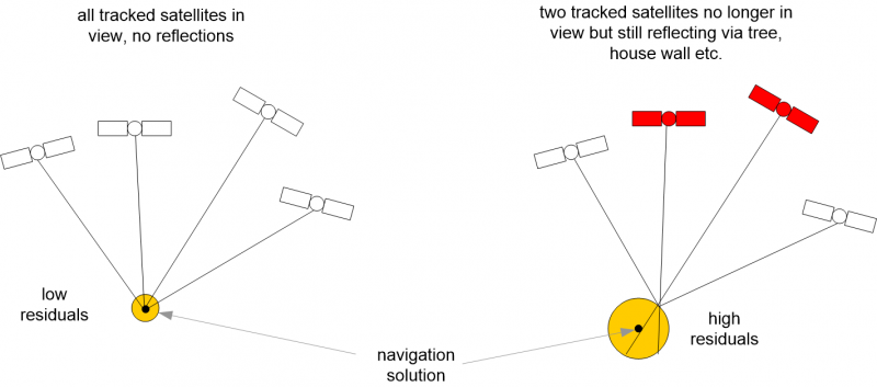
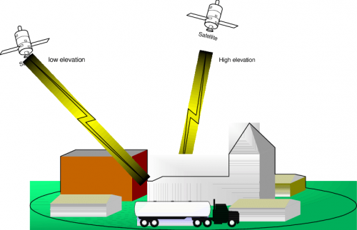
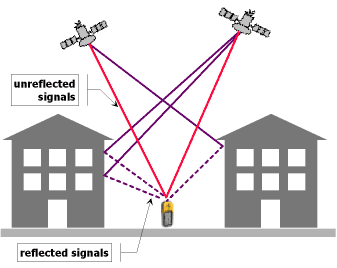
If you experience RTK float-to-fix recovery issues (no fix after timeout), or if you experience (slightly) false-fix solutions, the problem might be satellite reflections in the navigation solution:
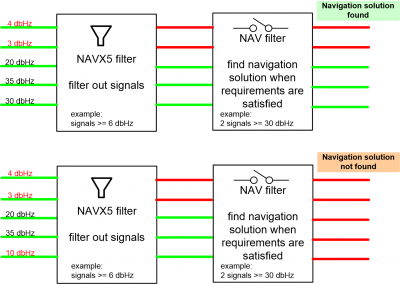
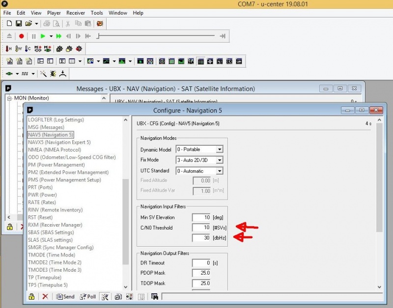
The solution to this problem is to configure a carrier to noise ratio filter (dBHz) like below (to filter out satellite reflections for a navigation solution). It is assumed that reflective signals have a significant lower signal strength than direct satellite signals.
Default navigation input filters settings:
 Min SV Elevation: 10 [deg]
 C/N0 Threshold  : 0  [#SVs]
                   0  [dbHz]
More restrictive navigation input filters settings (this will filter/reduce satellites required for a GPS navigation solution!):
 Min SV Elevation: 10 [deg]
 C/N0 Threshold  : 10 [#SVs]
                   30 [dbHz]
Min SV Elevation: Minimum elevation of a satellite (SV) above the horizon to start a navigation solution. Low elevation satellites may provide degraded accuracy, due to the long signal path through the atmosphere.
C/N0 Threshold: A navigation solution will only be attempted if there are at least the given number of satellites (SVs) with signals at least as strong as the given threshold.
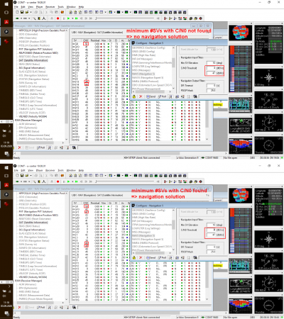
These parameters were discovered experimentally using a GPS trajectory test with limited sky view and reflections:
Tip: You can use u-center to monitor the signal strength (CN0/dbHz) etc. of all satellites discovered by the GPS receiver:
If you want to look for the signal strength (CN0/dbHz) of the sent frequencies (L1,L2 etc.), you can do this as well:
GPS checksum errors
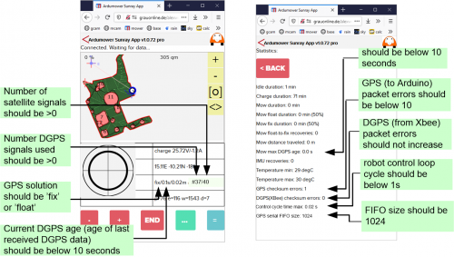
If your robot position jumps sporadically and you experience ublox GPS receiver-to-Arduino transmission checksum errors ('GPS checksum errors') shown in App under Statistics->GPS checksum errors:
or shown in the Arduino serial monitor:
Arduino serial monitor:
10:40:58.012 -> ublox chka error, msgclass=1, msgid=14, msglen=24: 5!=7F
10:41:58.036 -> ublox chka error, msgclass=1, msgid=14, msglen=24: 29!=C
10:42:58.019 -> ublox chka error, msgclass=1, msgid=14, msglen=24: 2A!=DC
10:43:58.033 -> ublox chka error, msgclass=1, msgid=14, msglen=24: 5!=FF
10:44:58.001 -> ublox chka error, msgclass=1, msgid=14, msglen=24: 8A!=44
10:45:58.023 -> ublox chkb error, msgclass=1, msgid=7, msglen=5C: B5!=27
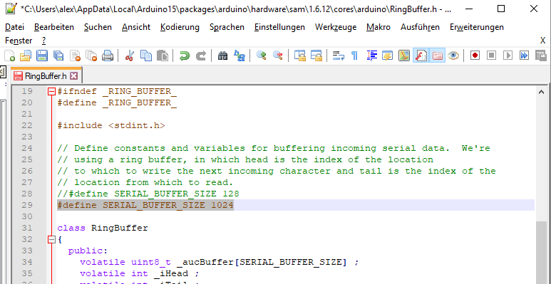
...then you might have to increase the Arduino serial buffer FIFO size:
- In Arduino IDE->File->Preferences Click on 'preferences.txt' at the bottom
- For Arduino Due: locate file packages/arduino/hardware/sam/xxxxx/cores/arduino/RingBuffer.h
- For Adafruit Grand Central: locate file packages/adafruit/hardware/samd/xxxxx/cores/arduino/RingBuffer.h
- Change: #define SERIAL_BUFFER_SIZE 128 into into: #define SERIAL_BUFFER_SIZE 1024
- Recompile and re-upload the Arduino sketch
Example where the Arduino serial buffer FIFO size has been increased:
XBee RF bandwidth/corruption issues
The described GPS message rates below are now configured automatically in the Sunray firmware. Please skip this section.
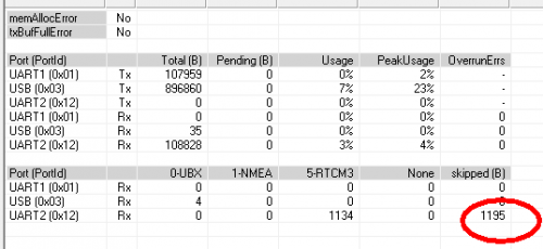
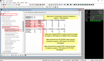
We experienced that the XBee mid-range radio modules (2.4 Ghz) have a very limited bandwidth, activating the RTCM3 messages at highest rate (1 Hz) at the base may not work stable and data corruption can occur at the rover and the rover is not getting a stable RTK FIX. You can verify this by looking at the rover's MON-COMMS message using u-center or by looking at the App's 'DGPS(Xbee) checksum errors':
If the skipped bytes is increasing at a high rate (compared to the received bytes), your base (or rover or both) XBee is sending too much data and you can reduce the bandwidth at the base by reducing the message rates.
For the XBee mid-range modules the following rates have shown to reduce bandwidth and we were able to get a robust RTK FIX all the time:
---- base RTCM3 message rates ---------------
rate
10    1005: Stationary RTK reference station ARP
1     1074: GPS MSM4
2     1084: GLONASS MSM4
3     1094: GALILEO MSM4
0     1124: Beidou MSM4
2     1230: GLONASS code-phase
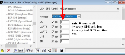
You can change the message rates at the base via the configuration of the CFG-MSG message, choosing the above RTCM3 messages and setting zero (0) to turn a a RTCM3 message off or a non-zero rate value for the message rate. For example setting the rate to 1 means every GPS solution, 2 means every two GPS solutions etc. Do not forget to send and save the base configuration.
Addendum: another possible reason for limited bandwidth might be that the rover module is sending too much (unnecessary) data to the base, so stealing RF bandwidth. You can verify this using ucenter. Make sure that the rover is only sending the NMEA message GGA via UART2 (if you use NTRIP) with rate 60 or disable any outgoing messages for UART2 (if use your own base). You can change the messages sent via the configuration of the CFG-MSG message (see screenshot above).
Long-range and 10% duty cycle
The XBee long-range (LR) modules for Europe comply with the EU 10% duty cycle regulation (ETSI EN 300 220-2 V3.1.1) meaning that they radios do not send more than 10% of the possible data rate each second (among all channels). So, if e.g. we would encounter too much CRC errors at the GPS receiver XBee port it would proably mean the XBee sender was trying to send more than the 10% cycle (in a second), however the XBee module limited the traffic and stopped sending after the 10% resulting in a CRC error at the GPS receiver. So the best is to look if there are any CRC errors at the receiver to ensure the amount of data fits into the 10% cycle.
GPS antenna selection guide
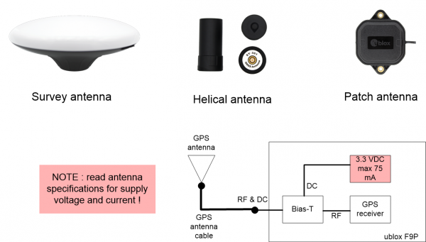
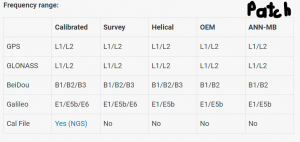
We are currently experimenting with different GPS antennas for the rover. Generally, all antennas can be used in all environments. In very difficult environments, best fix-solution results have been reported by using the Survey antenna.
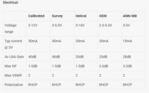
gain of different multi-band antennas:
Survey GNSS Multiband antenna:       40 dB
Helical antenna for multiband GNSS:  33 dB
Patch antenna for multiband GNSS:    28 dB
IMU, sensor fusion
Tip: Please operate your mower without IMU first (skip this section) and add an IMU later (if everthing else is working).
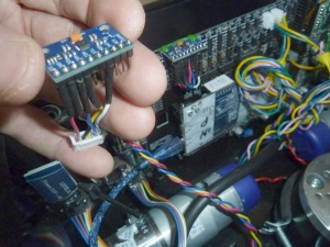
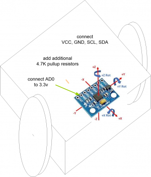
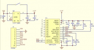
Optional (highly recommended): You can install an IMU (MPU6050 / MPU9150 / MPU9250 / MPU9255) like shown below to improve short-term direction measurements (in addition to wheel odometry). You can mount the IMU anywhere in the Ardumower chassis (location/position does not matter however orientation does matter! Have a look at the drawing below for correct orientation, the +X axis is pointing forward).
NOTE: IMU support has not been tested thoroughly (for a longer duration) yet. Make sure to configure the correct module in 'config.h'. For the shop module, choose MPU9255 in 'config.h'. If you IMU was found correctly, you should hear 8 short buzzer beeps at the mower start (automatic gyro calibration).
Remember: Set PCB1.3 jumper JC2 (VCC/I2C signal level) to 3.3V for IMU connector (if not set correctly you may experience I2C issues)
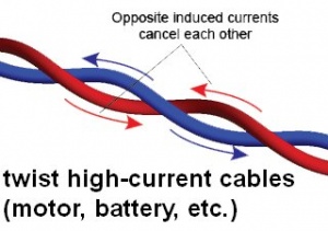
IMPORTANT: The I2C bus (SDA, SCL) is sensitive to EMI caused by motors etc. - For robust I2C bus communication results, keep the I2C cables away from motors! (see photo below) and twist all 'high-current' cables (motor, battery etc.):
![]() The IMU chip is sensitive to heat, avoid hot-glueing on the module or near the chips, otherwise you may damage the IMU module!
The IMU chip is sensitive to heat, avoid hot-glueing on the module or near the chips, otherwise you may damage the IMU module!
1. Connect PCB1.3_I2C2_VCC(5V/3.3V) to IMU VCC (set PCB1.3 JC2 VCC/I2C signal level jumper to 3.3V)
2. Connect PCB1.3_I2C2_GND to IMU GND
3. Connect PCB1.3_I2C2_SDA to IMU SDA (set PCB1.3 JC2 VCC/I2C signal level jumper to 3.3V)
4. Connect PCB1.3_I2C2_SCL to IMU SCL (set PCB1.3 JC2 VCC/I2C signal level jumper to 3.3V)
5. Connect PCB1.3_I2C2_3.3V to IMU AD0
NOTE: If you experience increasing 'IMU recoveries' (shown in the App under statistics), you can try out dividing the pullup values in half by attaching the IMU module to PCB1.3_I2C4 (instead of PCB1.3_I2C2). I2C2 has no pullups, but I2C4 does have 10k pullups. Together with the 10k pullups on the IMU module this will divide the overall pullup values in half to 5K.
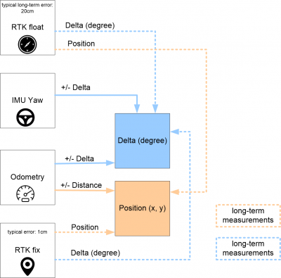
The following image shows how the sensor fusion of all data (RTK GPS, odometry, IMU) happens:
Click here to see a video on how to verify your IMU sensor is working correctly
Ultrasonic sensor
Optional: You can install up to three ultrasonic sensors like below to add obstacle detection (in addition to the GPS feedback-based obstacle detection).
PCB1.3 wiring (SonarL, SonarC, SonarR):
Ultrasonic Module VCC (+5V)  — PCB VCC (+5V)
Ultrasonic Module GND        — PCB GND
Ultrasonic Module Trigger    — PCB Trigger
Ultrasonic Module Echo       — PCB Echo
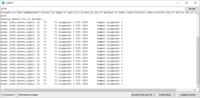
Note: You can test the ultrasonic sensors using the sensor test. Start Arduino serial monitor and send 'AT+F' (with ENTER) to the Arduino to start the sensor test.
Bumper sensor
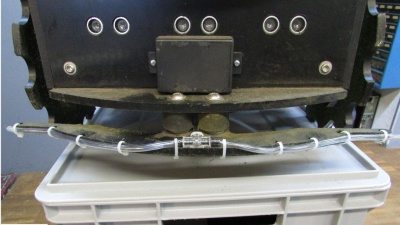
Optional (highly recommended): You can install a bumper bumper switch to add obstacle detection (in addition to the GPS feedback-based obstacle detection).
You can find more details about the bumper kit here: https://wiki.ardumower.de/index.php?title=Ardumower_Bumper
Note: You can test the bumper sensor using the sensor test. Start Arduino serial monitor and send 'AT+F' (with ENTER) to the Arduino to start the sensor test.
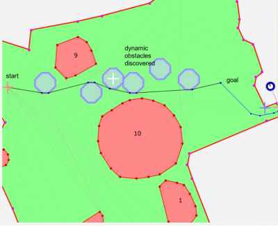
Obstacle detection and avoidance: For each detected (dynamic) obstacle, the robot firmware will set a temporary (dynamic) obstacle in front of the robot (shown in blue) and compute a new route from the current start position to the current goal position around all static and dynamic obstacles. Once the robot has reached the current goal position, all temporary obstacles are removed. NOTE: The robot will not transmit any obstacle data to the app, the given image is just for understanding of the obstacle avoidance.
The mowing starting point is defined during map calculation. The first mowing point will be as close as possible to the current robot position during the map calculation phase. If the robot cannot reach a certain point during mowing (e.g. due to discovered obstacle), it will discard the point in front of the discovered obstacle, put an virtual obstacle on its own map and try to drive around that virtual obstacle. If during navigation it discovers another obstacle, it will add another virtual obstacle and so on. If for some reason the area is filled with too many virtual obstacles so that the robot cannot reach the goal behind the first obstacle, it will state "no map route". Other reasons for the "no map route" state are GPS jumps. Once in the "no map route" state, the GPS will be reset, all virtual obstacles will be cleared, and the robot tries again. After 3 unsuccessful tries ("no map route"), the robot will go into error state.
Extending WiFi range with outdoor access point
These WiFi access points have been tested and are recommended for outdoor use (and typically have an extended range):
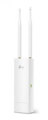
- TP-Link EAP110 (or EAP 225) Outdoor 2.4 Ghz 300 MBit outoor access point
- Ubiquiti UniFi UAP-AC-M Wireless Access Point
- ...
Portable WiFi router for NTRIP
For your first NTRIP tests (or even as permanent installation), you might use a portable 4G/WiFi router. Such 4G modem could be used where the WiFi coverage is limited. In addition, you can operate multiple WiFi devices (Ardumower PCB WiFi module, NTRIP client WiFi module, ESP32-CAM WiFi module etc.) via this portable 4G WiFi router. NOTE: You may have to use virtual private network (VPN) protocol to be able to access all devices from the Internet. Using VPN, the 4G router will connect to some VPN server (e.g. your private Fritzbox) and also provide an WiFi access point (AP) to all Ardumower WiFi modules. Both the robot and the App can then use the connected VPN server to connect to. Without a VPN server, an additional server would be required to access the robot from within the Internet and the VPN server satisfies this requirement.
Here are some example devices:
- HUAWEI E8372 WiFi/WLAN LTE Modem (only needs USB power)
- ...
Charging process, longer battery operation time
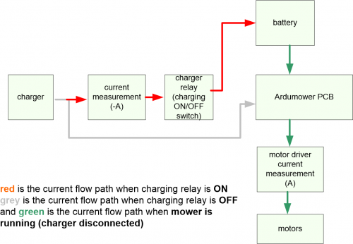
What electrical current does the App measure and show when in charging (App shows '-A') and mowing mode (App shows 'A')?
This is how the charging operation should look like in the Arduino IDE serial monitor / SD card log file:
volt=24
enableCharging=1   (charging relay is turned ON)
volt=24, chg=0.2   (charging current is flowing into the battery)
...some time later...
volt=25, chg=0.2   (charging current is flowing into the battery)
...many time later...
volt=28, chg=0.0   (no significant charging current is flowing into the battery)
enableCharging=0   (charging relay is turned OFF)
A note about the state 'charge' (indicated in the App): The robot will enter the state 'charge' once it measured a voltage at its charging pins. After the battery has been charged, the PCB charging relay is turned off (the battery is no longer charged), however the shown state will still be 'charge' (indicating the robot is still connected to the charger).
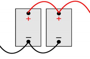
Tip: for longer battery operation time, connect two Ardumower batteries in parallel:
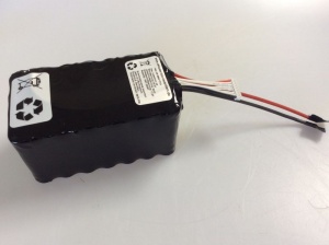
Or much easier: There are now two variants of the Ardumower battery pack, 125 Wh(5Ah) and 250 Wh(10Ah): https://www.asn-shop.de/Ardumower-Rasen-Roboter-Akku
Automatic robot switch off
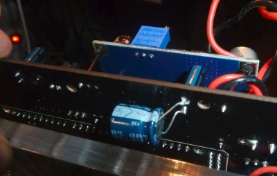
You can set jumper JP8 to 'Automatic' (near DC/DC module) to enable automatic robot switch-off for a) undervoltage and b) if the robot is in idle mode (you can choose both situations in config.h). If you enable automatic robot switch-off, it is recommended to add an additional capacitor (100 uF or higher, 63V) below the existing capacitor as shown below to be able to flash the Arduino without a sudden PCB switch-off. If not added the additional capacitor and automatic robot switch-off activated, you will have to press and hold the 'robot switch-on button' during the flash process.
Docking
Using a docking station available in the shop, (=two docking pins connected with your charger), your robot can go charging automatically.
Docking station building steps: https://wiki.ardumower.de/index.php?title=Charging_station Ideas for building a docking station: https://forum.ardumower.de/threads/ladestation-aus-aluprofilen.23905/ Further building ideas: https://wiki.ardumower.de/index.php?title=Charging_station
Docking App tutorial: https://youtu.be/iCrBT6e1tw0?t=1220
Docking/undocking demo video 1: https://www.youtube.com/watch?v=GRlvjBs7_tg
Docking demo video 2: https://www.youtube.com/watch?v=PSbmBYGLZBA
Docking prototype video: https://www.youtube.com/watch?v=03seYUKiJcc
Steps to use docking/undocking in the App:
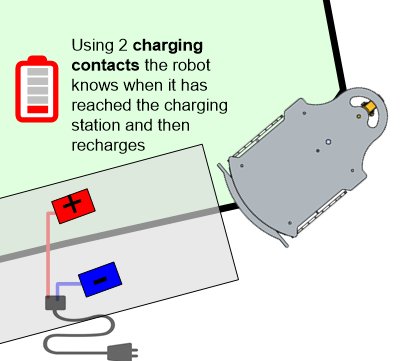
1. Place the docking station (indicated by the blue dot) within the mowing area or max. 2m away from the mowing area. Place the docking station far away (>2m) from larger obstacles like walls etc..
2. Record docking points: Activate Record mode: dock in the App, then manually steer your robot mower from a position with good sky view (good GPS signal) (first docking point) into the docking station until the docking contacts (last docking point), and add docking points via the App during this process.
NOTE: The last docking point (for the docking contacts, shown bigger) should be moved slightly (30cm) behind the actually docking contacts via the App point editor mode (symbol [.]), so the robot tries to reach it (and it doesn't matter if it cannot actually reach that point). Also, the docking point should get a good GPS fix solution at all times.
3. After recording docking points, upload map to the mower.
4. To undock, the mower must have touch to the docking contacts (the App shows 'charge'). Then press 'Start' in the App to undock. The mower will drive in reverse out of the docking station to the first docking point and continue at the last mowing point (or start at the first mowing point) . If there is no touch to the docking contacts, the mower will think it is out of the docking station and drive directly to the mowing point without actually undocking. Note that no GPS float solution is used during undocking. Only IMU and odometry and (if available) a GPS fix solution is used during undocking.
5. To dock, press 'Dock' in the App. The mower will calculate a path to the first docking point, and then follow the docking points until the docking contact.
How much energy does the robot consume in the docking station? For your information, here are power consumption measurements when the robot is not charging the battery:
Ardumower PCB1.3 with Bluetooth + WiFi + RTK-GPS: 7 Watt (RTK-GPS: 1.5 Watt, WiFi: 1 Watt, Arduino Due: 2 Watt)
WiFi module
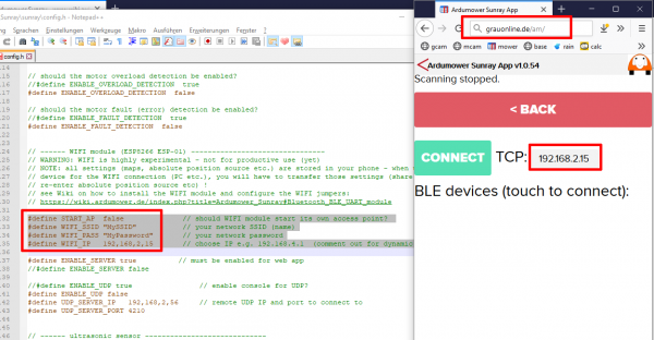
Optionally, you can add a ESP8266-01 WiFi module (using ESP8266 NONOS SDK V2.2.1 firmware) found in the shop to your PCB1.3 and use it with the Sunray firmware. The computer browser (client) will communicate directly with the mower (server). So, the mower acts as HTTP server (TCP port 80) and the App as HTTP client (via web browser).
computer browser (HTTP client) ==> Mower (HTTP server, TCP port 80)
Demo video: https://www.youtube.com/watch?v=onsTfae-8VQ
Related topics: Sunray App connection issue solved (forum link)
NOTE: all settings (maps, absolute position source etc.) are stored in your phone - when using another device for the WIFI connection (computer etc.), you will have to transfer those settings (share maps via app, re-enter absolute position source etc)!
NOTE: Never connect with two devices (e.g. computer and phone) at the same time! (Close the App on the phone before using WiFi on the computer)
WiFi module (ESP8266)
- Ensure your ESP module is using firmware 2.2.1 (https://www.espressif.com/en/support/download/sdks-demos) like the Marotronics module
- Make sure you have set the WiFi jumpers (shown here).
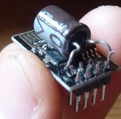
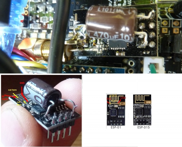
- If you experience connection issues, you may have to add an additional capacitor (e.g. 470 uF/10V) to the module as shown in the photo. Also, do not use additional cables in between PCB1.3 and WiFi module if you experience connection issues.
- Look into firmware file config.h on how to configure SSID and (a static) IP.
- Look into the serial console (Download section, step 7) if you experience connection issues and to debug the connection process.
- If your home router does not allow servers within your home network, on your router, you may have to allow the mower IP address to receive packets via TCP port 80, so the App (client) can send packets directly to your mower (server)
- If you experience map upload errors in the App, check section above (GPS checksum error) on how to increase Arduino serial FIFO size.
Flashing WiFi module (ESP8266)
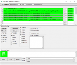
- If you need to change the ESP8266 firmware use the following tool: https://www.espressif.com/en/support/download/other-tools (Flash Download Tools).
- Ensure to download 'ESP8266 NONOS SDK V2.2.1 firmware' (https://www.espressif.com/en/support/download/sdks-demos)
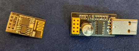
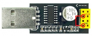
- Before starting the flashing procedure, GPIO_0 must be connected to Ground for the entire flashing procedure to enable programming mode. The pins can be found here : https://components101.com/wireless/esp8266-pinout-configuration-features-datasheet. The configuration of the download tool looks like this (ignore the firmware version used in the screenshots):
- More information about the ESP8266 variants (unrelated to our project): http://stefanfrings.de/esp8266/
Bluetooth Low Energy (BLE) and WiFi external antenna
You might use an ESP8266 (ESP-07) module like this and an external antenna from Marotronics (not tested by the Sunray author):
- ESP8266 (ESP-07): https://www.marotronics.de/ESP8266-WIFI-Wlan-Serial-Module-ESP-07
- antenna: https://www.marotronics.de/24-Ghz-Wireless-Antenne-mit-sma-Anschlusskabel-zB-fuer-ESP8266
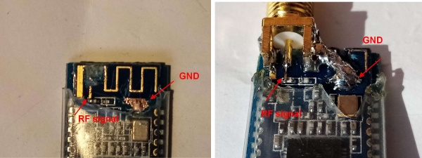
Alternatively, this might be the right hack for you (tested by the Sunray author) :-) This is how I added an external SMA antenna (SMA female socket, SMA-male-to-female extension, SMA male antenna) to the Bluetooth 4.0/BLE UART module (CC2540) to increase range to approx. 20m. Happy hacking :-)
And this is how I added an external SMA antenna (SMA female socket, SMA-male-to-female extension, SMA male antenna) to the ESP8266-01 WiFi module
![]() WARNING! Modifications to RF antennas, RF signal pathes on PCB's etc. are risky and you will loose general permission to operate the device - you may radiate additional unknown signals due to your modifications. Be warned of that! Tip: If you want to measure the performance of your antenna, you can use a 'RF antenna vector impedance/standing wave ratio measurement tool' (e.g. PS100/N1201SA).
WARNING! Modifications to RF antennas, RF signal pathes on PCB's etc. are risky and you will loose general permission to operate the device - you may radiate additional unknown signals due to your modifications. Be warned of that! Tip: If you want to measure the performance of your antenna, you can use a 'RF antenna vector impedance/standing wave ratio measurement tool' (e.g. PS100/N1201SA).
What are the differences between the Ardumower and ArduSimple ublox receiver configurations
ArduSimple base/rover PCB port connections:
 UART1: connected to Ardumower PCB1.3 (rover only)
 UART2: connected to XBee module
 USB:   connected to computer (u-center)
Ardumower base (ublox F9P) configuration (identical with ArduSimple base config):
PRT (ports) protocol UART2 (XBee) in:     RTCM3
            protocol UART2 (XBee) out:    RTCM3
            baudrate UART2 (XBee):        115200 baud
RATE (rates) measurement period:          1000ms (1 Hz)
TMOD3 (Time mode3) mode:                  Fixed mode
  Fixed Position:                         Your base lat/lon coordinates
MSG (messages) for UART2 (XBee)           transmit frequency (10 means message is sent every 10 solutions):
  F5-05 RTCM3.3 1005 Stationary ARP       1
  F5-4A RTCM3.3 1074 GPS MSM4             1
  F5-54 RTCM3.3 1084 GLONASS MSM4         1
  F5-5E RTCM3.3 1094 GALILEO MSM4         1
  F5-7C RTCM3.3 1124 Beidou MSM4          1
  F5-E6 RTCM3.3 1230 GLONASS code-phase   1
Ardumower rover (ublox F9P) configuration:
additional activated messages (or changed message frequency) for UART1+USB:
MSG (messages) for UART1(Ardumower)+USB   transmit frequency (60 means message is sent every 60 solutions)
  F0-00 NMEA-GxGGA                          60
  01-07 UBX-NAV-PVT                         10
  01-12 UBX-NAV-VELNED                      1
  01-14 UBX-NAV-HPPOSLLH                    1
  01-3C UBX-NAV-RELPOSNED                   1
  01-43 UBX-NAV-SIG                         10
  02-32 RXM-RTCM                            5
additional activated messages for UART2(XBee)+USB:
  MSG (messages) F0-00 F0-00 NMEA GxGGA     60
RATE (rates) measurement period:            200ms (5 Hz)
PRT (ports) baudrate UART1 (Ardumower):     115200
            baudrate UART2 (XBee):          115200
            protocol in UART1 (Ardumower):  UBX+NMEA
            protocol out UART1 (Ardumower): UBX+NMEA
            protocol out UART2 (XBee):      NMEA
            protocol in UART2 (XBee):       RTCM3
NAV5 (navigation 5) input filter:
  Min SV elevation                          10          default:  10
  C/N0 Threshold #SVs                       10                     0
  dbHz                                      30                     0
Troubleshooting
- XBee: The GPS->XBEE blinks at the base but the XBEE->GPS does not blink at the rover. Ensure that your XBee modules are configured correctly (see XBee configuration section further below).
- Adafruit M4: The firmware does not boot and there is no output in the console. Ensure that you have both pull-up resistors connected and that they have proper contact. If you have shrinkable tubing around the wires, check that there is no breakage within. Ensure that battery voltage is not too low (or remove battery - the PCB also works without battery).
- The battery is not been loaded. If the battery voltage is too low, then the board cannot load the battery. Disconnect battery and charger from the mower and connect the charger directly to the battery.
- You cannot see the Blutooth BLE module listed in the App via 'Connect'? If not, ensure that you give the App Bluetooth permissions.
- Can you drive the mower via the App 'manual control' without any issues? If not, verify the motor odometry settings via a motor test (see odometry section above).
- Does the mower have issues to rotate ('delta' shown in the App ) correctly and is it missing an IMU? If yes, add an IMU (e.g. 9250, see IMU section above).
- Do you get constant 'IMU tilt' errors and cannot get rid of them? Your IMU may be broken. Check forum on how to verify your IMU (see below).
- Do you sporadically get 'IMU timeout' errors? See IMU section above on how to shorten IMU cables. Also, check RTC battery (I2C bus will not work well with low RTC battery).
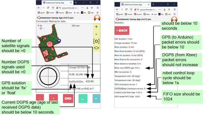
- Does the 'GPS checksum error' shown in the App (Statistics) increase or does the robot position jump sporadically? If yes, check section above (GPS checksum error) on how to increase Arduino serial FIFO size.
- Does the RTK position (N,E shown in the App ) jump after a mower restart and are you using NTRIP/SAPOS? If yes, verify you are using absolute position mode in the App (see position source mode section above).
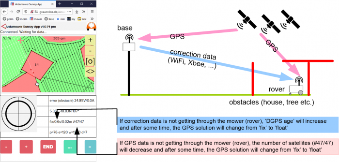
- Does the 'DGPS age' shown in the App increase too much (>5 seconds)? If yes, verify your WiFi or XBee connection (see section extending outdoor WiFi above on how to improve WiFi connection). Also, verify the LEDs on the GPS modules - at the base, the LED 'GPS->XBEE' should blink and on the rover, the LED 'XBEE->GPS' should blink. Also, verify that your base is configured for 'Fixed Mode' and is getting a '3D' position solution (see section 'RTK base / Your own RTK base' above).
- Does the 'DGPS checksum error' shown in the App (Statistics) increase? If yes, verify your WiFi or XBee connection (see section XBee corruption issues above).
- Is the 'number of DGPS signals used' show in the App (example: #37/40 means 37 signals where DGPS was used versus 40 total signals) almost zero, or even zero (0/0)? If so, your base is not sending sufficient correction signals or the rover could not use the DGPS signals.
- Do you sporadically get 'GPS invalid' solutions? If yes, verify your WiFi or XBee connection (see above sections extending outdoor WiFi and XBee corruption issues). Also, verify your PCB1.3 DC/DC module voltage output.
- Do you get GPS invalid (after some time) that never returns back to a float or fix solution at locations where it normally does quickly? Or is the LED 'XBEE>GPS' flickering and not blinking? If so, your GPS module might be broken and it's advisable to try another one.
- Do you have issues to get a 'fix' during manual steering and recording your map? If yes, wait for a fix, take your time and always drive the mower slowly.
- Do you have issues to get a 'fix' during automatic mowing? If yes, try out Hartmut's ublox config (found in Sunray GitHub).
- Do you still have issues to get a 'fix'? Use a ground plate (10x10cm) and connect it to PCB ground.
- Does the 'control cycle time max' shown in the App (Statistics) increase too much (>0.02s)? If yes, your WiFi access (or something else) may slow down the robot control loop too much and robot tracking errors may appear (example: a max. conrol cycle of 1s would mean the robot motors were running without active control for max. 1s).
- Do you seem to get correction data at the rover without enabling your own base? It might be possible that someone else is operating a sender too in your area (10 km). Look at section 'your own base station' above how to change the network ID of your XBee long-range modules in both rover and base modules.
- Do you get an error 'no map route'? Verify, the map has been uploaded, your robot is placed inside the perimeter and the GPS position (visualized by a white circle) is correct and inside the perimeter too. Also, verify the odometry is configured correctly (see section odometry test above) and verify the sensors are working correctly (see section bumpers/sonar sensor test further above). Also, verify your IMU is working correctly (see IMU section further above).
-
IMU sensor tilt issues: https://forum.ardumower.de/threads/imu-tilt-error-9250.23864/
GPS/RTK WiFi NTRIP and RTK non-stable fix issues:
No FIX after ublox FW upgrade:
ublox f9p firmware upgrade guide:
How to record GPS data
For debugging purpose, all data sent by the ublox receiver (and received by the Ardumower PCB) can be recorded into a file via u-center. This log file can then be used to play back again the recorded data. So, it simulates the GPS receiver used during the recording.
Before recording, ensure all messages are enabled for USB too:
1. Connect your laptop computer (Windows) to the simpleRTK2B rover module USB port marked as 'POWER+GPS'.
2. Download ublox u-Center v21.05, install it and start it: Download link
3. Choose 'Receiver->Connection' and choose your rover module COM port.
4. Choose menu 'View'
5. Choose 'Configuration View'
6. Click on 'MSG (Messages)' at the message list most left
7. Choose message '02-32 RXM-RTCM'
8. Add 'USB On' there (add checkmark for USB)
Do the same for messages:
01-07 UBX-NAV-PVT
01-12 UBX-NAV-VELNED
01-14 UBX-NAV-HPPOSLLH
01-3C NAV-RELPOSNED
01-43 NAV-SIG
02-32 RXM-RTCM
0A-36 MON-COMMS
9. Save configuration:
10. Click on 'CFG (configuration)' at the message list most left
11. Ensure 'Save current configuration' is selected
12. Click on 'Send' button at the bottom
Steps to record your GPS receiver data:
1. Click on red 'record button' and choose a file name for the recording.
2. If being asked to save the receiver configuration, choose 'No' to skip that.
3. Now everything is not only sent from the GPS receiver to the Ardumower PCB but also saved in the record file. After finished the session, press stop button to stop recording.
Datasheets
Here you can find allowed LoRa (long-range) frequencies for each country as well as datasheets for the XBee and ublox modules.
North America: XBee XLR Range module, 915 MHz, up to 50 km, max. 120 Kbps (Xbee PRO SX MCQ-XBPSX)
Global: XBee Mid Range module, 2.4 Ghz, up to 300m, max. 250 Kbps (Xbee XB24CASIT-001)
SR/LR/XLR world frequencies:
- Global: 2.4 Ghz/433 MHz (some restrictions)
- North America: 315/915 MHz (902-928MHz)
- South America: 433 MHz
- Europe: 433/868Mhz (863-870MHz)
- Africa: 433 MHz
- Asia: 415/433 MHz
- China: 470/433/779/920 MHz (779-787MHz, 920-924MHz)
- Japan: 426/920 MHz (915-930 Mhz)
- Australia: 433/915 MHz (915-927MHz)
- New Zealand: 917-927MHz
u-blox GNSS Antennas Application note (UBX-15030289)
ublox Multi-band, high precision GNSS antennas (ANN-MB series)
u-blox F9 high precision GNSS receiver interface description
Data privacy
When sharing your maps in the App, all data is saved anonymously and without any GPS coordinates. All position data is saved only as distance (North, East) in meters between the recorded points and your base. All data is kept confidential and according to German protection of data privacy. It is not possible to identify any locations or any persons with this anonym data.
Discussion / questions / forum thread
If you have any doubt, or if you are unsure, please ask in the Ardumower forum for help:
Link to forum: https://forum.ardumower.de/forums/sunray-firmware.22006/
SD card module
Optionally (highly recommended), you can add an SD card module (found in the shop) to your Arduino Due and use it with the Sunray firmware to save uploaded maps or log serial output data.
NOTE: The Adafruit Grand Central M4 already has an SD card reader built-in.
The SD card reader can be connected directly to the Arduino Due SPI pins.
Wiring:
CATALEX MicroSD card Adapter     Arduino Due SPI pins
CS    -------------------------  Arduino Due pin 46  (chip-select pin, not an SPI pin)
SCK   -------------------------  SCK
MOSI  -------------------------  MOSI
MISO  -------------------------  MISO
VCC   -------------------------  5V
GND   -------------------------  GND
SD card logging
For the very rare case that the Arduino hangs/stucks at a certain library, the watchdog in the Arduino has been programmed by the Sunray firmware to reset the Arduino.
However, if this reset happens too often, and you have the feeling it is a software issue, SD card logging might help to find out the code location for the hang/stuck.
IMPORTANT: For a full inspection, we will need both, your log files AND your compiled binary (sunray.ino.elf) !
1. Insert a FAT32 formatted microSD card into the Adafruit Grand Central M4
2. Activate SD card logging in your config.h
3. Locate the compiled 'sunray.ino.elf' file and make a copy of it (because Arduino IDE will delete the binary when closed):
3.1. In Arduino IDE, enable 'full output during compilation and upload' via menu File->Preferences
3.2 Compile the sunray.ino file
3.3 Look into the Arduino IDE output to find out the location of the compiled 'sunray.ino.elf' file
3.4 Using Windows Explorer, go into the shown folder and make a copy/backup of the 'sunray.ino.elf' file.
4. Run your robot. If some unexpected RESET appears, the Arduino will automatically save additional 'stack dump' information in the log file that corresponds to your compiled binary (sunray.ino.elf). Therefore the stack dump information only makes sense for your compiled binary.
For further inspection, send us both your SD card log files AND corresponding binary (sunray.ino.elf).
Developers/users can inspect the stack dump (found in the log files at the top) as follows. The stack dump contains RAM addresses that the CPU uses when calling a sub-function to remember the code address where to get back after completing that sub-function. By inspecting the stack addresses one can list all code locations (until the point where the CPU is running).
1. Locate the ARM GDB debugger in your Arduino Adafruit package and run it on the binary file (sunray.ino.elf):
> C:\Users\alex\AppData\Local\Arduino15\packages\adafruit\tools\arm-none-eabi-gcc\9-2019q4\bin>arm-none-eabi-gdb
     c:\users\alex\AppData\local\temp\arduino_build_408598\sunray.ino.elf
2. To list the code for an arbitrary address found in the stack dump, use the GDB list command - Example: the stack dump contains address '0x8732' and you want to find out if that is a valid code address and what code is at that address:
(gdb) list *0x8732
R/C model
In addition to the App, you can steer the robot via an R/C model controller. The R/C pinout (P13) is:
P13_1  +5V              ----- R/C model controller VCC
P13_2  GND              ----- R/C model controller GND
P13_3  pinRemoteMow     ----- R/C model controller speed and direction channel (forward/backwards)
P13_4  pinRemoteSteer   ----- R/C model controller steering channel (left/right)
P13_5  pinRemoteSpeed   not used
P13_6  pinRemoteSwitch  not used
To activate R/C mode, power on robot and press START button (P20) for 3 seconds. Press again START button (P20) for 3 seconds to turn off R/C mode.
Hardware debugging
For the very rare case that the Arduino hangs/stucks at a certain library, the watchdog in the Arduino has been programmed by the Sunray firmware to reset the Arduino.
However, if this reset happens too often, and you have the feeling it is a software issue, hardware-debugging might help to find out the code location for the hang/stuck.
In the Github folder 'openocd' ( https://github.com/Ardumower/Sunray/tree/master/openocd ) you will find a 'readme.txt' that describes how to connect a Raspberry PI to the Arduino for hardware-debugging. The idea is to set a 'breakpoint' at the watchdog interrupt for the case that the Arduino resets. The hardware-debugger (Raspberry PI in this case) can then be used to get a backtrace of the last function calls to locate the problem in the code.
XBee module configuration
The XBee modules (LR/XLR) on ArduSimple PCB's are already configured. If you need to reconfigure for some reason, here's how to do so:
- Connect ArduSimple PCB USB (XBee side) to your PC
- Download XCTU software: https://drive.google.com/file/d/1Xm7pnVrxbnvwYuVfX84T3tMu2N2Fy2ne/view?usp=sharing (OR: https://www.digi.com/xctu)
- Start XCTU
- Windows: If your the COM port for the XBee is not found, start Windows device manager, right-click on XBee USB device, choose 'update driver->find on this computer->choose from list on my computer' and finally choose 'Digit International->Digi USB Serial Port'
- In XCTU, choose 'Add radio module specifing the port settings' and choose the COM port
- Settings found on the XBee SX 868 (Firmware version A007) - The sections marked in red are important:
- NOTE: If you experience resets of your Xbee with the latest XCTU software, you have to use XCTU software version 6.5.6. You can find older XBee XCTU software here: https://drive.google.com/file/d/1Xm7pnVrxbnvwYuVfX84T3tMu2N2Fy2ne/view?usp=sharing
Channel Mask: 3EFFFDFF
Network ID: 1985
Broadcast Multi-Transmits: 3
RD Data Rate: 80 kps
TX Power Level: 32 mW
Unicast Retries: A
-
Routing/Messaging Mode: Standard Router[0]
Broadcast Hops: 0
Network Hops: 7
Mesh Unicast Retries: 1
-
Destination Address High: 0
Destination Address Low: FFFF
Transmit Options: 40
Node Identifier:
Network Discovery Back-off: 82
Network Discovery Options: 0
Cluster ID: 11
-
Encryption: Disabled [0]
AES Encryption Key:
-
Baud Rate: 115200
Parity: No Parity [0]
Stop Bits: One stop bit [0]
Packetization Timeout: 3
Flow Control Threshold: 11D
API Enable: Transparent Mode [0]
API Options: API Rx Indicator - 0x90 [0]
-
DIO0: Commissioning Button
DIO1: Disabled
DIO2: Disabled
DIO3: Disabled
DIO4: Disabled
DIO5: Assoc. Indicator
DIO6: Disabled
DIO7: CTS flow control
DIO8: Sleep Request
DIO9: ON/SLEEP Output
DI10: RSSI PWM0 Output
DI11: Disabled
DI12: Disabled
DOUT: UART_DOUT
DIN:  UART_DIN
DI15: SPI_MISO
DI16: SPI_MOSI
DI17: SPI_SSEL
DI18: SPI_SCLK
DI19: SPI_ATTN
Pull Direction: FFFFF
Pull-Up: FFFFF
PWM0: 0
PWM1: 0
Associate LED Blink Time: 0
RSSI PWM Timer: 28
-
Sleep Mode: Normal
Sleep Options: 2
Number of Cycles Between Sleep: 1
Sleep Time: 190
Wake Time: 1F40
Wake Host Delay: 0
Firmware Console Debugging
 Here you can find out more details about boot process and how to find connection errors (e.g. firmware boot stuck, Bluetooth/WiFi not connecting, GPS corruption errors etc.) using the serial console:
https://docs.google.com/document/d/14qa15AKLG0EUfNJKfFPwAsKfrLlM0yoqJ1TyiM5c9Fk/edit?usp=sharing
Further links
- Stanford University GPS course:
https://scpnt.stanford.edu/research/current-research/gps-mooc
https://www.youtube.com/watch?v=o1Fyn_h6LKU&list=PLGvhNIiu1ubyEOJga50LJMzVXtbUq6CPo
