AzuritBer Firmware (English)
Inhaltsverzeichnis
- 1 GITHUB Location
- 2 Test requirements
- 3 What is AzuritBer and Why
- 4 Possible Option
- 5 Standard Setup
- 5.1 Install Firmware in DUE
- 5.2 Arduremote or PFOD APP
- 5.3 Main
- 5.4 Command
- 5.5 Console
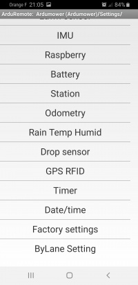
- 5.6 Setting
GITHUB Location
It's here:
Process is the same as AZURIT :
You need to upload all file to your PC and open ardumower.ino into arduino IDE.
Upload the code inside your DUE :
On first start it's possible that EEPROM is empty (PCB Beep and start with ERROR) so you need to reset error counter and save setting.
Test requirements
![]() Security note: For security reasons, always remove mower blades in your first tests!
Security note: For security reasons, always remove mower blades in your first tests!
![]() Important: For your first wheel motor tests, jack your robot so that the tires can run freely without ground contact!
Important: For your first wheel motor tests, jack your robot so that the tires can run freely without ground contact!
Prerequise to follow this WIKI: BT Module connected on PCB1.3 (ESP32 is also possible) and Pfod or Arduremote running into Android phone
What is AzuritBer and Why
AzuritBer was build for DENNA,ROBOMOW and PARANELLO platform and use Odometry or IMU to control the state change. It can only run on DUE and Odometry is mandatory (minimum 400 ticks per rev).But it's possible to adjust setting to work on other platform.
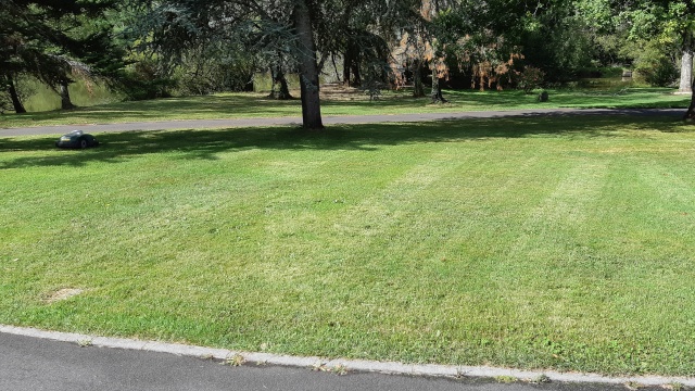
This version always use odometry into all movement (reverse,roll etc...) .The result is a more smooth movement without pause between all the différents state and the possibility to mow by lane for big area and faster mowing
Here video of the random mowing behaviour on 2 platform:
2 Usefull option are Raspberry PI and RFID module.
At the beginning of the dev i need many debug message to perfectly adjust the firmware, so i add a raspberry and record all the mowing duration in a Console. Actually PI is optional, but help a lot to find trouble in the behaviour and to communicate (With your PC,or home automation) Other option is the RFID tag reader
Possible Option
WIFI ESP32 Sender
Full description of the new sender is here:
https://wiki.ardumower.de/index.php?title=WIFI_Perimeter_Sender(English)
if you have only one mowing area , you can use sender from shop : sender start when mower leave station and stop when mower is back or after a 5 hours timeout.
But if you want to use RFID and multiple mowing area, Firmware need to control sender over WIFI and you need the new sender based on ESP32
WIFI and MQTT
Full description is here :
AzuritBer_ESP32_option_(English)
RFID READER
Full description is here :
AzuritBer_RFID_option_(English)
Raspberry PI
Full description is here :
AzuritBer_Pi_Firmware_(English)
You can connect a Raspberry Pi to arduino DUE USB native port
Optional 5 inch tactile screen can easily control all the mower and show many info on last mowing run.
It's possible to access to mower from your Wifi and set everything from your Sofa (Including firmware upgrade)
Home Automation can control the mower using MQTT message and start mowing according your automation.
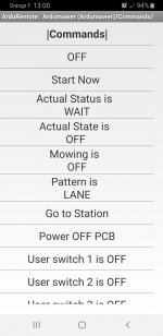 Bluetooth or WIFI (need esp01 connected on PCB1.3) control using arduremote
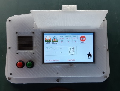 Manual control using tactile screen
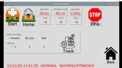 WIFI control using VNC Viewer (https://www.realvnc.com/fr/connect/download/viewer/) from your sofa
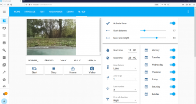 WIFI control using mqtt and compatible software (here Home Assistant https://www.home-assistant.io/)
Standard Setup
Hardware is standard one : the PCB1.3 or 1.4 and simple BT module HC05
The mower can run in full automatic mode inside a perimeter wire.
Software add the ByLane and Wire mowing .
Start using timer at different location on the perimeter wire with 3 possible mowing behaviour: Mow wire,Random Mode or By Lane Mode
You can Acces to mower using Arduremote or Pfod over Bluetooth.
Install Firmware in DUE
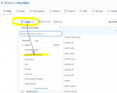
In Github repo the MASTER version is the GY-521 version and the latest one.
According your IMU module select the correct firmware from Github (GY-88,GY-87 and MPU-9250 are possible) by switching the branch.
Note that the MPU-9250 is not always working perfectly (Noise on DC Motor freeze I2C line),On some 9250 chips you can see randomly I2C RTC error .So it's better to use GY-88 or GY-521 (More noise tolerant ??)
If you see some freeze : first test for 2 or 3 hours with mow motor deactivate to be sure the motor noise is not too important.
After unzip the github repository ,open the ardumower folder and the ardumower.ino. Before uploading the sketch ,verify that into mower.h the line :
*          #define Console Serial
*          //#define Console SerialUSB
are set like that : uncomment #define Console Serial to receive Console message inside your PC arduino ide console and comment #define Console SerialUSB
Upload sketch inside DUE using programming port.
Arduremote or PFOD APP
To control mower with a phone or tablet you need to use a software named ARDUREMOTE.
You can easily install it using the Play Store from your phone
Main
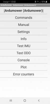
If BT or WIFI connection is OK you can see main menu from Arduremote :
Command
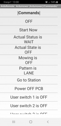
Arduremote
Command menu is the mostly used menu to start and stop the mowing cycle manually.
OFF is used to stop immediately the mower.
Start Now start the mowing cycle according pattern selection.
Actual Status state and mowing are only readable value and change when mower run.
Pattern is is used to select what you want the mower cycle do:
Possible value are :
LANE -> mower mow in parallel lane according lane setting
RANDOM -> mower change to a new random direction each time the wire is detected or bumper is hit or motor sense is too high.
WIRE -> mower track the wire and mow the border of the area until find the station.
GO TO STATION is used to send mower to charging station without mowing.
POWER OFF PCB Power off all the mower.
USER SWITCH are optional setting.
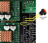
Button connected on P20
The Button connected on P20 is an easy mower command and work like that:
If mower is in OFF state:
Push less than 1 sec = start mow in LANE
Push it 2 seconds = start mow in RANDOM
Push it more then 3 Seconds = GO TO STATION
If mower is running:
Push it to stop immediately
Console
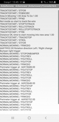
When you use the soft Without Raspberry PI Option, if you don't understand some behaviour ,it's possible to use console.
Console show all the message you need for understanding why mower stop or reverse or roll etc....
Setting
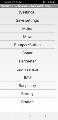
Here the setting page.
Only For the first start, or with a new RTC eeprom :If you have error, you need to go into arduremote COMMAND and click on OFF to stop beep and in main menu ERROR COUNTER reset all error,next into setting, do a save setting.
Power OFF the PCB , do not forget also to disconnected the USB PC cable to be sure all restart correctly.
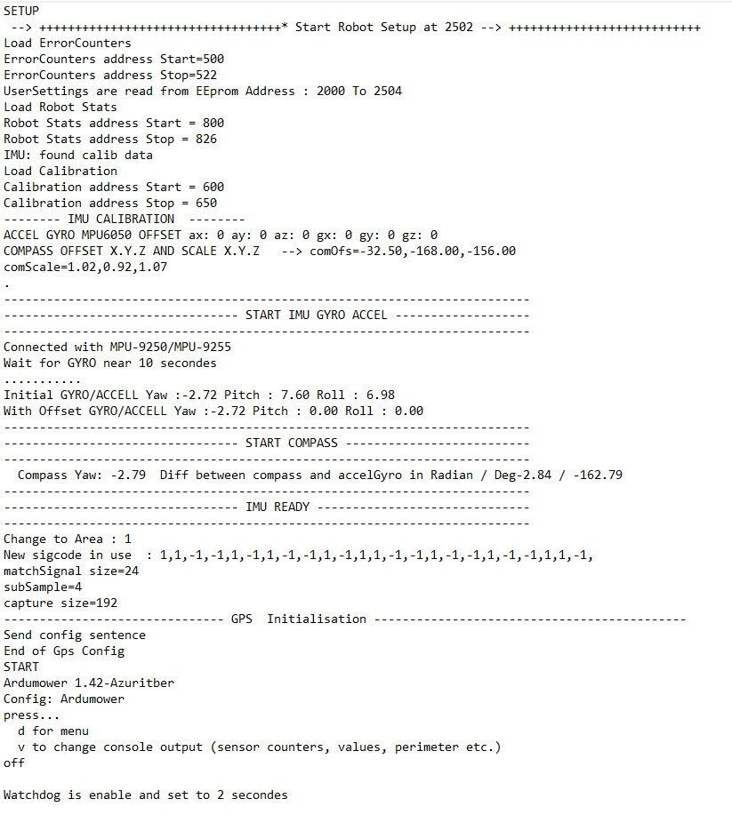
Restart with PC connected on Due programming Port and the Ide console speed is set at 115200 bps .
ARDUINO IDE CONSOLE SHOW (it's example using MPU9250 imu) :
![]() ****** SAFETY ****** Go To : Main Menu / Setting / Mow Motor
****** SAFETY ****** Go To : Main Menu / Setting / Mow Motor
Set Force mowing off to YES
ODOMETRY Setting
3 Values are require and need to be set in this order:
Value 1
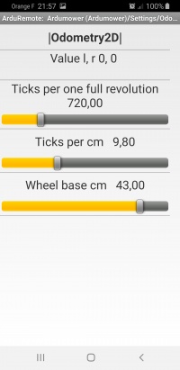
Go To : Main Menu / Setting / Odometry
You need to set the correct ticks per one full revolution and check the result
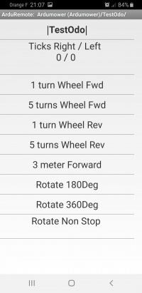
Go To : Main Menu / Test ODO
Use 1 turn Wheel FWD
The wheel need to accelerate ,roll , brake and stop after exactly one revolution.
Sample video : https://youtu.be/BV7MgO6jfwA
CONSOLE SHOW:
Repeat the test with 5 turn Wheel FWD to be sure.
Value 2
Back To : Main Menu / Setting / Odometry
Now you need to set the correct Ticks per cm according the diameter of the wheel.
you can find the value by this formula: Ticks per one full revolution / (PI*diameter of the wheel)
In this example the DENNA platform (diameter wheel is near 23 cm) : 720/(3.1415*23)=9.9
So perimeter of the wheel is 3.1415*23 = 72.25 cm
Ticks/cm = 720/72.25 = 9.96 ticks/cm
Back To : Main Menu / Test ODO
Now use the 3 meters Forward command to see if the value is OK.
Here the video : https://youtu.be/v-yzRV4FEWA
The mower need to run forward for 3 meters .Adjust the value again if result is not 3 meters +/-10 cm
Value 3
Back To : Main Menu / Setting / Odometry
Now you need to set the correct Wheel Base in cm .
It's the distance between the 2 wheels. It is use to compute correctly all the mower roll movement.
Back To : Main Menu / Test ODO
Now use the Rotate 180 Deg and Rotate 360 Deg to verify the setting.Adjust the value again if result is not at +/- 5 Deg.
Here the sample video : https://youtu.be/9uUA2qCqlrA
Mower need to rotate according your choice.Change the Wheel Base in cm until you find 180 and 360 degrees
MOTOR Setting
Go To : Main Menu / Setting / Motor
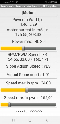
First set the POWER MAX to 100 to be sure the motor don't stop.
Set PWM max speed for example to 150 (Put mower on the mowing area in flat location and with 4 meters free forward) click Calib Ticks/Second to approach the correct RPM value from PWM one ,mower need to move and compute and save the new RPM value.
You can now repeat this step until find the correct value fo rPWM and RPM.
Each time you change PWM max value you need too calibrate again the ticks per second (Not needed for RPM)
RPM is use into manual mode and auto forward mode, so to check a new value simply go to Main Menu / Manual and drive forward.
PWM is use into automatic mode on all small movement (Rev,Roll,accel etc..) and need to be enough for the mower to move smoothly.
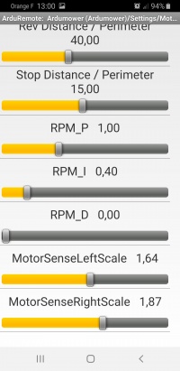
If the wheel don't roll smoothly in manual forward ,maybe you need to adjust the RPM_P RPM_I and RPM_D
See PID Control : [1]
Always start with RPM_D=0 and move the 2 sliders RPM_P and RPM_I. RPM_P increase the changing speed and RPM_I smooth the speed when near the RPM max speed.
You need to find a correct Manual / forward drive before continue with the Power max setting.
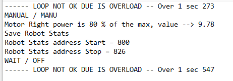
Remember that at 80% of the power max the mower react like if a bumper is pressed.
When PWM is OK you can adjust the power max value ,simply deactivate bumper and In Manual / Forward stop the mower with your foot, normally the mower stop before the wheel slip. State change to OFF and into console you can see the according message.
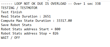
CONSOLE SHOW with max power=12:
Do not forget to reactivate the Bumper.
Slope Adjust Speed Set to YES if you have slope on your mowing area it's help to have same Motor speed in Uphill and Downhill.
Actual Slope Coeff if Slope Adjust Speed is YES this real time value can change from 0.8 to 1.2 according Downhill and Uphill (Normaly near 1.00 on flat location)
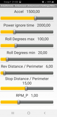
Power ignore time On motor start the sense can have a peak. During this delay the sense is not read.
Roll Degrees max Into random mowing and after the mower find the wire and reverse it roll randomly with this maximum value.
Roll Degrees min Into random mowing and after the mower find the wire and reverse it roll randomly with this minimum value.
Rev Distance / Perimeter is the distance that mower drive after cross the perimeter wire to return inside mowing area (Always > Stop Distance / Perimeter).
Stop Distance / Perimeter is the distance that mower drive after cross the perimeter wire before stop.
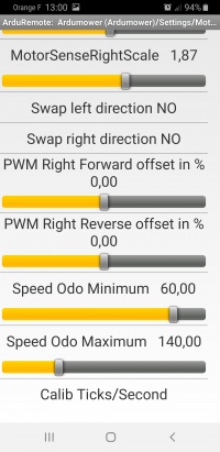
MotorSenseScaleLeft and right are here to help to have a real Power, but the main is that at 80% of Power max : mower stop and reverse.
Swap Left Direction and right need to stay to NO and it's better to directly invert the motor wire + and -
PWM Right Forward Offset if the right and left motor don't rotate exactly at the same speed , You can use this setting to adjust and repeat the test ODO 1 rev forward until the 2 wheel stop at the same time.
PWM Right Reverse Offset Same setting but when mower reverse.
Speed ODO Minimum Important setting : it's the minimum PWM that the firmware send to motor to have a movement.If too low the mower make pause between movement, if too high the movement are not perfectly smooth.
Speed ODO Maximum help on very small movement (less the 1/4 rev wheel)
Calib Ticks/Second You need to do this once. The mower run forward for 1 or 2 wheel rev and compute the ticks / second. It is used on each movement to know the duration of the state according to the distance you want to drive.
MOW setting
![]() ****** SAFETY ****** Go To : Main Menu / Setting / Mow Motor
****** SAFETY ****** Go To : Main Menu / Setting / Mow Motor
Set Force mowing off to NO or the blade never run and BE CARREFULL THE BLADE RUN
Go To : Main Menu / Setting / Mow
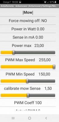
Mow motor can run at different speed according the high of grass.It's directly link to motor sense. So you need to correctly set the max power of mow motor to have everything working correctly.
Remember that at 80% of max power, mower start to mow in spiral mode, and at 100% of max power during 1 sec the motor is stop for more than 1 minute and restart automatically after, at a very high power the error hardware driver motor can also occur and you need a full power off to restart the mow motor
To adjust everything try to find a location with medium high grass and low grass:
Set the Power max to a small value (15 Watts for example)
Set the PWM Max speed to 255
Set the PWM Min speed to 150
Start to mow in auto mode in the low grass (The mow motor need to start at PWM=255 and reduce slowly during the next 10 seconds),now send the mower in high grass ,normally motor speed increase and spiral mowing start.
If the spiral mowing start on low grass increase the Power max setting.
Like for drive motor you can use calibrate mowsense to have a realistic sense,but the main is that mow spiral start on high grass and mow motor stop on overload in VERY HIGH GRASS.
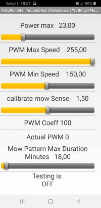
PWM coeff and actual PWM are actual (read only) value of the motor modulation.
Mow Pattern Max Duration is used to change from Random mowing mode to Bylane mowing mode and avoid track on the mowing area.(The mower switch the 2 mode every 18 minutes in this case)
STATION setting
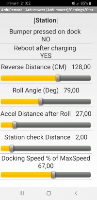
Station is blocking one , so the mower need to reverse to leave it.
In schedule mode or start from station, mower use (IN THIS ORDER) reverse distance, Roll Angle and accel Distance after Roll to leave the station and start to find again perimeter wire to locate the mowing entry location according the timer setting, or track 1 meter if manual start from station.
On Go Home mode mower track the wire and find the station (A voltage is detected on charging pin, or Bumper is pressed) it stop immediately and slowly go forward for the Station check Distance to be sure the contact is OK.
If you use Right Sonar, the docking speed is reduce according to % of MaxSpeed each time something is detected while tracking the wire.
On full schedule mode it's better to activate the Reboot after charging, by this way all variable are restore and everything work for week or month without any intervention.
PERIMETER setting
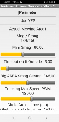
Main value is Mag and is negative when mower is inside area (near -2000 if mower inside and upper the wire). In this case(139) the mower is outside at 3 meters of the wire.
Mini Smag:
Under this value the firmware estimate that the sender is OFF, so it's error. To find the correct value simply put the mower in the area and unplug the sender (Read the Smag and add 20 or 30 , use slider to adjust MiniSmag)
Check by start mowing and unplug the sender: Mower need to stop rapidly and go to error.
Timeout(s) if outside :
Big AREA Smag Center
Help mower to not generate In/OUT transition in the middle of big area. To find correct value ,simply put the mower in the middle area as far as possible from the wire and use Smag value.
Tracking Max Speed PWM
it's the tracking speed (lower value help to have a smooth tracking on curve)
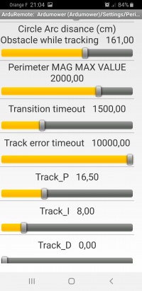
Circle Arc Distance...
If mower find obstacle while tracking : it reverse,Roll 45 Deg and make a circle to find again the wire.
Perimeter MAG MAX VALUE
Put mower directly upper the wire and use here the maximum Mag value.
Transition Timeout
When tracking,Mower need to change from inside to outside using the PID, but if it fail after this transition time one wheel is stop to find again the wire. If too important the mower can fail tracking on 90 deg angle .
Track Error Timeout
If mower can't find In/OUt transition during this delay it's error.
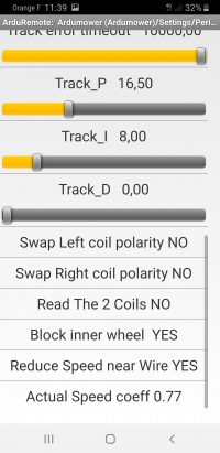
Track PID
The Pid is use to smooth the tracking and need to be adjust according your platform (Distance between wheel and receiver coil,motor react speed etc..)
Coil Polarity
Do not change ,It's better to invert the wire at sender output.
Read the 2 coils
Only for dev test : Do not change
Block inner wheel
If YES the 2 wheels always roll forward , if NO one wheel can reverse to find again wire on big angle for example.
Reduce Speed Near Wire
If YES mower reduce the forward speed when near perimeter
Actual Speed Coeff
It's the real time value of speed ratio when mower approach the wire
IMU Wiring and Setting
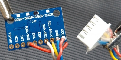
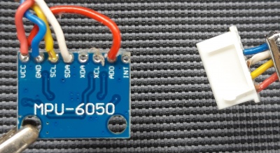
MPU-9250 IMU WIRING TO PCB1.3
MPU-9250 or 55 is not really stable (can work many hours or fail after some minutes without any particular reason) ,so it's better to use GY-88 / GY-521 + GY-273 more stable module
 IMU       PCB
 VCC <---> 3.3V
 GND <---> GND
 SDA <---> SDA
 SCL <---> SCL
 ADO <-> IMU VCC
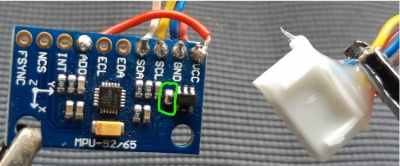
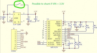
Optional : It's possible to shunt the onboard DC/DC converter (NEVER PUT 5V on VCC with this option)
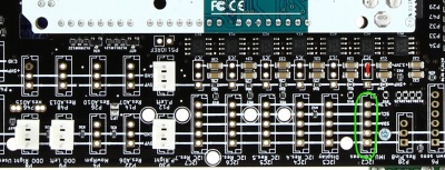
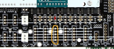
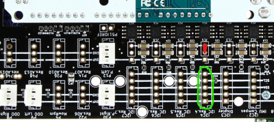
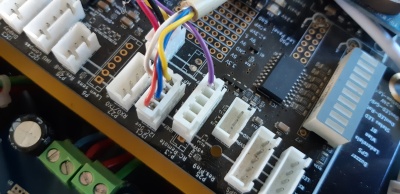
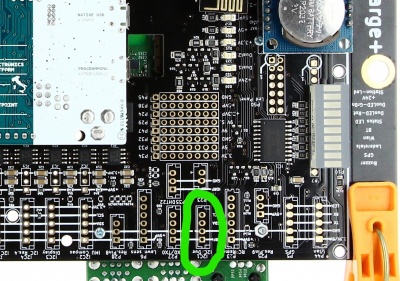
Connect module on I2C2 IMU Compass and do not forget JC2 jumper to 3.3V
If you have some I2C error it's also possible to connect IMU on other location like I2C5 and JC5 to 3.3V to have a different pullup resistor.
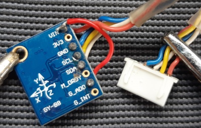
GY-88 IMU WIRING TO PCB1.3
 IMU       PCB
 VCC <---> 3.3V
 GND <---> GND
 SDA <---> SDA
 SCL <---> SCL
 G_ADO <-> IMU VCC
Connect module on I2C2 IMU Compass and do not forget JC2 jumper to 3.3V
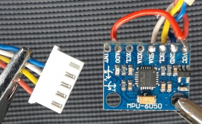
GY-521 ACCEL/GYRO WIRING TO PCB1.3
IMU       PCB
 VCC <---> 3.3V
 GND <---> GND
 SDA <---> SDA
 SCL <---> SCL
 ADO <-> IMU VCC
Connect module on I2C2 IMU Compass and do not forget JC2 jumper to 3.3V
GY-521 don't have compass ,so you need to deactivate Compass into arduremote/setting/IMU or add a GY-273 module
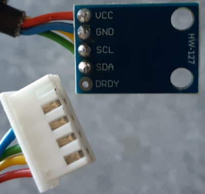
GY-273 COMPASS WIRING TO PCB1.3
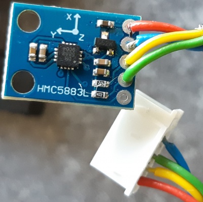
On the net you can find different module with fake chips like this one (Note HMC5883L on PCB but it's a QMC5883L),so you need to set the correct compass name into mower.cpp if it don't work with standard setting.
IMU       PCB
 VCC <---> 3.3V
 GND <---> GND
 SDA <---> SDA
 SCL <---> SCL
Connect module on I2C4 port and do not forget JC4 jumper to 3.3V
GY-273 is a compass that you use with GY-521 you need to activate Compass into arduremote/setting/IMU.And do not forget to calibrate it.
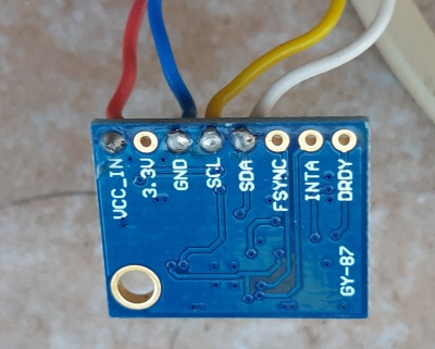
GY-87 WIRING TO PCB1.3
 IMU       PCB
 VCC_IN <---> 3.3V
 GND <---> GND
 SDA <---> SDA
 SCL <---> SCL
On GY-87 you can't change I2C adress and it's the same as RTC so you can't connect it on normal I2C port.
Connect module on I2C1 I2C_DUE
Select the correct firmware into Github
IMU Main Setting
More info on IMU ,But no sensor fusion and not the same calibration process : Azurit_Firmware_(English)#IMU
Here the video of IMU running to keep the heading : https://youtu.be/gxCrIb5geJM
Imu (except GY-521) is composed by 2 parts : Compass and Gyro/Accel.
Compass use magnetic earth field and is disturb by all motor and electronics in the mower, so it's very difficult to have correct value (for example a change of 10 deg is possible if you move the mower for only 1 deg). But it's reliable (If indicate 25 Deg and roll for 360 deg or wait 10 minutes it's always 25 Deg)
Gyro/Accel is very accurate (+/- 1 or 2 deg) but can drift over time, (If indicate 25Deg and you wait 5 minute it can be 30Deg, but when you rotate slowly the mower you can see that everything is OK from 0 to 179 and from -179 to 0 Deg)
The firmware can use or not the compass (Simply test and use the best according the location of the IMU in your platform)
If GY-88/GY-87/GY-521 IMU are used ,you need to calibrate GYRO/ACCEL on the initial installation: Simply Go To Setting / IMU, press the ACCEL/GYRO initial calibration and wait 1 or 2 minutes without moving the mower (Arduremote lost connection during the process and it's normal if arduino ide is connected you can see the process in the console).
For MPU/9255 or 9250 this process is automatically done on each start of the mower,so you can't see the button in arduremote .
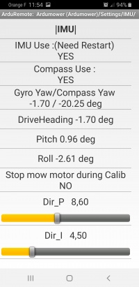
IMU Use
Use or not the IMU (By lane require IMU to work correctly).
Compass Use if you use GY-521 alone, you need to deactivate compass.Or if your IMU is locate near electronics or motor you can't calibrate it correctly ,so it's better to deactivate compass : Bylane mowing can result on drifting in parallel lane without compass but not always an issue in normal mowing condition.
Compass don't add a very important behaviour, so it's better to not use it or be sure that the Compass yaw result is not perturb by motor magnetic fields.
Stop Mow Motor During Calib
It's possible to stop the mow motor to avoid compass noise but not really useful.
P I D
Like for the motor the PID need to be adjust if the mower don't drive smoothly in straight lane, Try to change the mower heading with your foot and normally the mower retrieve rapidly the precedent heading.
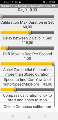
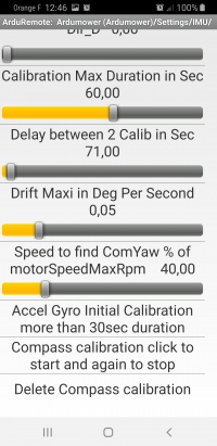
Calibration Max Duration
When mower stop to adjust the Compass value to GYRO/ACCEL , the drift is check,If the drift is always present ,Mower continue to mow after this delay,but only in random mode.
Delay between 2 calib
Each time this delay is trig ,Mower stop , roll to find the compass actual heading and stop again to check if the drift is small,If it's OK heading is automatically adjust to continue to mow in always the same direction from north for example.If compass is not activate ,only drift is check.
'Drift Maxi in Deg per Second
When mower stop to calibrate ,This value is used to restart or wait again until drift stop.
Speed to find ComYaw
At the begin of calibration, mower roll and read compass,but it's possible to reduce Roll speed to find easily a new value.
SETTING Without Compass
![]() ****** SAFETY ****** Go To : Main Menu / Setting / Mow Motor
****** SAFETY ****** Go To : Main Menu / Setting / Mow Motor
Set Force mowing off to YES
Set Compass Use to NO and leave all setting to default.In this case, Heading 0 is the start position of the mower
To check if it's OK:
Go To : Main Menu / Test IMU
Maybe you need to reduce the motor PWM max speed if the test fail sometime (The mower need to roll slowly)
Start to mow in random mode and change the mower heading with your foot (If IMU is OK The mower need to always keep the heading)
Without Compass you can see that the Bylane mowing is not perfectly parallel over time
Only the GYRO Yaw is updated in arduremote setting.
On Normal mowing mode you can see the mower stop every 'Delay between 2 calib' seconds and wait until the GYRO/ACCEL drift is inferior to 'Drift Maxi in Deg per second' value.If this process fail, mower continue to mow in random mode.
SETTING With Compass
Set Compass Use to YES and leave all setting to default.
You need To DO the Compass calibration each time you change IMU location in the mower or add metal/Magnet near IMU
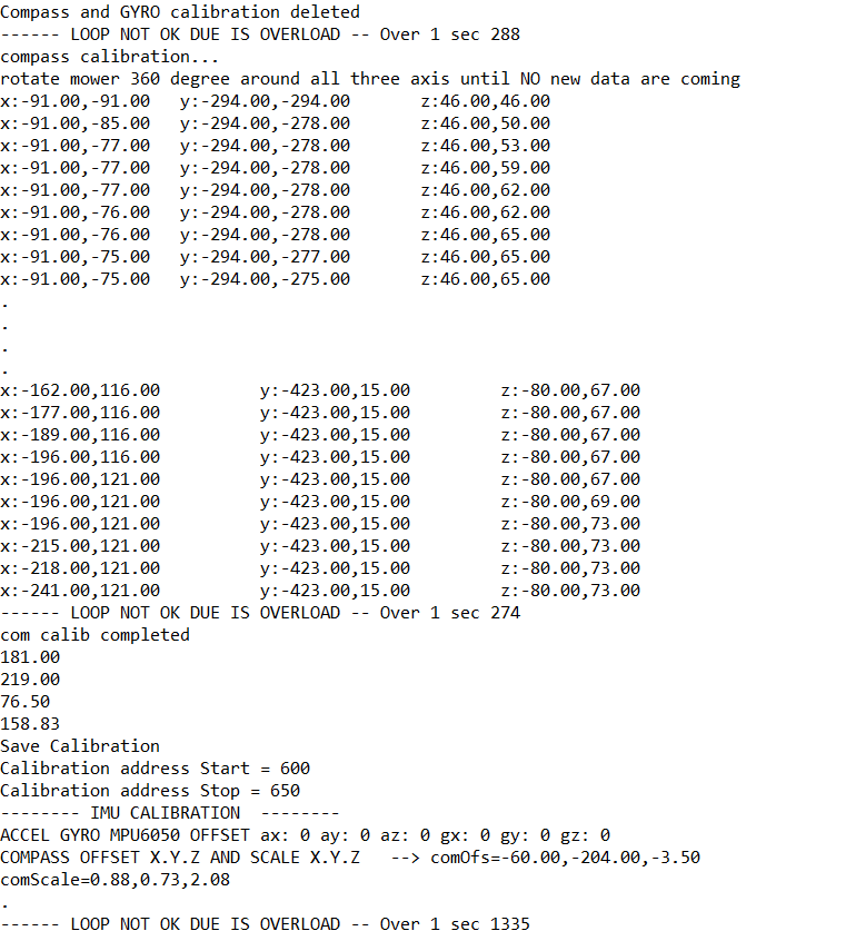
Start and stop the compass calibration : click one time to start and move the entire mower around all axes until no new data coming in the Console click again to stop and save the new calibration data.
CONSOLE SHOW :
Now on the setting Imu arduremote page you can see the GYRO Yaw and Compass YAW value according to magnetic earth field.It's normal to don't have the 2 same values after 10 or 30 seconds or after roll the mower.And you can discover the main difference between GYRO/ACCEL and COMPASS.
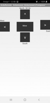
Heading 0 is normally North if no metal or magnet near compass.
On Normal mowing mode you can see the mower stop every 'Delay between 2 calib' seconds , Roll until the compass find the lane heading and wait until the GYRO/ACCEL drift is inferior to 'Drift Maxi in Deg per second' value.If this process fail, mower continue to mow in random mode.
TIMER setting
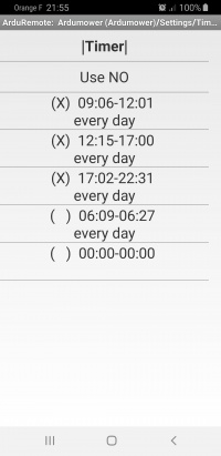
The Timer is used to mow in full automatic mode for month or week.Timer can be trigger only if the mower is not into charge state.
![]() When you use the Go To Station from Arduremote the mower return to charging station and stop to check the Timer for the next 1 or 2 hours.
To do test and reuse timer ,you need to send OFF from arduremote when mower is in the station and wait 1 minute to see the mower start again from station using timer setting.
When you use the Go To Station from Arduremote the mower return to charging station and stop to check the Timer for the next 1 or 2 hours.
To do test and reuse timer ,you need to send OFF from arduremote when mower is in the station and wait 1 minute to see the mower start again from station using timer setting.
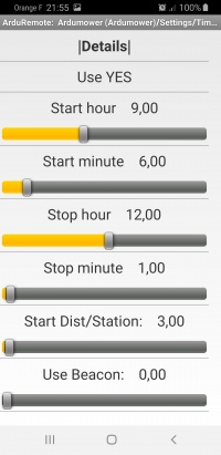
On the first page the Use NO at the top deactivate all timer and leave mower in station. Set it to yes and set up one of the 5 timer to make it work.
Always Avoid that one timer stop later than other start or the opposite,or you can see strange behaviour.
Start dist/Station is the distance the mower track the perimeter wire before start to mow.
Use Beacon is here to use with RFID fast start process.
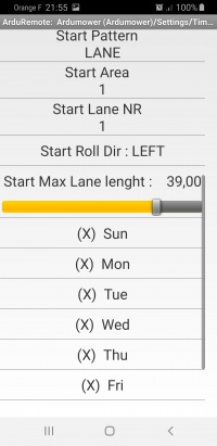
Start Pattern can be Wire(Mower start from station ,mow the entire wire and back in station for the next hour) , LANE (it's parallel lane mowing mode) or Random.
Start Area is used to select the correct mowing area, the Start dist/Station begin at the entry point of the new area.(ONLY POSSIBLE With RFID Option)
Start Lane NR can be 1 2 or 3 like you define in the By Lane setting.
Start Roll Dir is the roll direction Left or Right when the By Lane is in used.
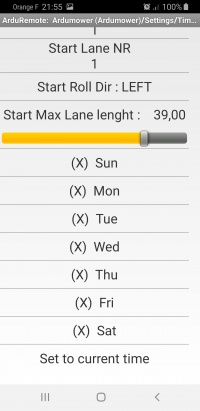
Start Max Lane Length is the distance max that mower drive on By Lane Mowing mode.
Set to current time help to fill the start and stop sliders.
BYLANE setting
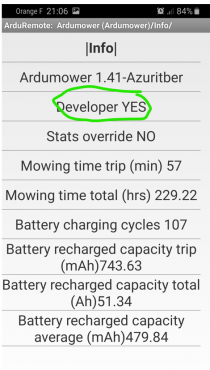
To have acces to all setting the Dev mode need to be activate:
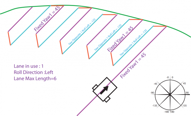
Using IMU and ODOMETRY mower can mow in parallel lane faster than random mode, but you need to correctly setup IMU to have good and fast result.
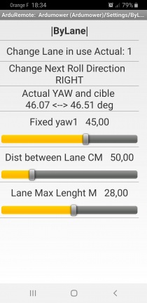
3 mains Lane are set ,Factory are 45, 90 and 135 degrees (Avoid value near 0). For each Lane 2 opposites reverse heading are possible according the ROLL dir at the end of the initial lane. So you need to adjust 9 angles, 3 for each lane.
Change Lane in use Click to use the next lane
Change next Roll Direction Click and mower change the next roll dir when reach the perimetr wire
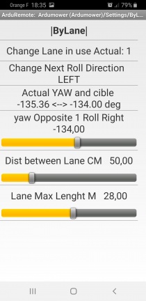
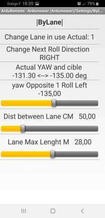
THIS Menu is Dynamic so Setting are made in live mode : Start to mow and see the menu changing (from Fixed Yaw to Yaw opposite right or left) each time mower stop and reverse,For first test : leave the Fixed Yaw to factory and adjust the left and right Yaw Opposite according the mower real time behaviour.
For example if for the lane 1 you set a fixed yaw to 45 deg, you can set Yaw opposite 1 Roll Left to -135 or -134 . In this case the mower mow perfect parallel lane (reverse heading is exactly the opposite of fixed one)
Other example if for the lane 1 you set a fixed yaw to 45 deg, you can set Yaw opposite 1 Roll Right to -120 , the mower mow in a kind of Zig Zag and go fast from one side of area to the other.
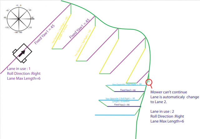
When mower is lock by a curve in wire perimeter (Red Circle in Picture) the Lane NR is automatically change and the IMU calibration start again to adjust Compass and GYRO, by this way it's possible to always mow on same heading in the garden.
Dist Between lane It's the distance between 2 parallel lane according the weight of your mower.
Lane Max length It help to reduce the error on IMU heading (Set length < 10 meters if you really want that mower mow perfectly parallel or set to max with a small difference in the 2 opposite YAW if you want to have a fast mowing mode,in this case it's not perfectly parallel but mow really faster)
BATTERY setting
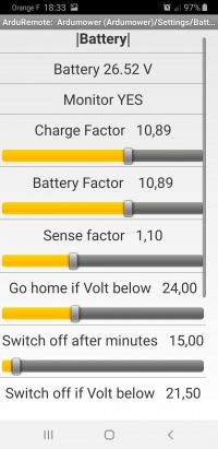
Use the Monitor option to auto stop the PCB and protect Battery.BETTER to leave it always YES. And always YES if there is no BMS into your battery pack.
Charge Factor
Coeff that help you to have a perfect value read from charging station voltage.
Battery Factor
Coeff that help you to have a perfect value read from battery voltage.
Sense Factor
Coeff that help you to have a perfect value read from sense charging.
Go Home if Volt below
In mowing mode the mower automatically return to station when battery voltage is below this value.
Switch off after minutes
When mower is OFF or in ERROR state, PCB automatically shutdown after this delay (REQUIRE JP8 in AUTO MODE)
Switch off if Volt below
PCB automatically shutdown if battery voltage is too low (REQUIRE JP8 in AUTO MODE)
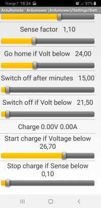
Start charge if Voltage below
When mower reach the charging station, the charging start and you can see the 2 values (Charge and sense just upper this line).Be careful when testing ,if the battery is not really empty the charge don't start each time, it's a electronic result (you can see the battery voltage increase very fast), but in normal working mode, all work perfectly.
Stop charge if Sense below
You can set here the minimum Sense that the battery drain at the end of the charging process.If too low the charging process is automatically stop after 5 hours and a message is send on the Console.
SONAR setting
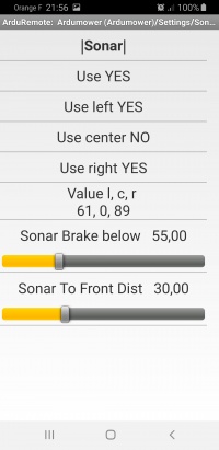
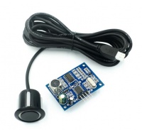
Firmware is tested for this type of Sonar : JSN-SR04T
Sonar can be used like a bumper : When trigge, mower speed is reduce and mower stop after the detection distance without hitting obstacle.
Or Sonar can simply reduce motor speed for the next 3 seconds.
Into mower.cpp you can simply change this line to true to change behaviour
sonarLikeBumper =false; //ultrasonic reduce speed vs bumper like
Sonar brake below
Only this distance is scan by the sonar.
Sonar To Front Dist
Distance between front of mower and sonar location, useful to never touch obstacle.
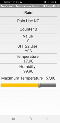
RAIN TEMP setting
Rain Use
set to YES if you want that Mower go to station when rain sensor is trig
DHT22Use
set to YES if you have connected a DHT22 sensor on PCB1.3.
Maximum Temperature
When DHT22 temp is upper this value the mower goes into ERROR and the PCB is totally power OFF. To be tested ,maybe bug here.
OLED Screen setting
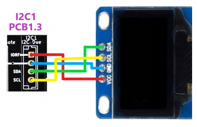
In AZURITBER Ver >= 1.6 It's possible to connect small OLED screen on the PCB1.3 I2C1 port
Resolution is fixed to 128 * 64 pixel and can use 1.3 or 0.96 pouce screen
The oled need to be I2C U8G2 compatible, so SSD1306 or SH1106 I2C model :
You need to Enable it into mower.h line 128
#define Enable_Screen true
*      //#define Enable_Screen false
And select the correct model into screen.cpp . Factory setting are for 1.3 Pouce model from Ebay.
U8X8_SH1106_128X64_NONAME_HW_I2C u8x8(/* reset=*/ U8X8_PIN_NONE);
U8G2_SH1106_128X64_NONAME_F_HW_I2C u8g2(U8G2_R0, /* reset=*/ U8X8_PIN_NONE);
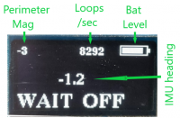
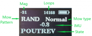
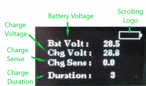
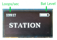
According the status of the mower Oled show different screen :
In OFF mode :
While mower running :
When Charging :
When into station waiting for next timer start :
