Ardumower LP
Inhaltsverzeichnis
- 1 Zusammenfassung
- 2 Benötigte Module
- 3 Hauptleiterplatte
- 4 Leiterplattenversionen
- 5 Leiterplatten Jumper
- 6 Leiterplatten-Module
- 7 Leiterplatten Steckverbinder
- 8 Stromversorgung
- 9 Download and flash Arduino code
- 10 First-time calibration
- 11 Diagnostics/troubleshooting
- 12 Starting the mower
- 13 Error counter / error beeps
- 14 Settings
- 15 Further links
Zusammenfassung
Diese Seite beschreibt,wie die Ardumower Hauptleiterplatte aufgebaut wird, wie das Programm auf den Arduino aufgespielt wird, undwie man den Mähroboter konfiguriert.
Kernstück der Steuerung ist ein fertiges Microcontroller-Modul (Arduino Mega 2560 verwendet 54 I/O pins).
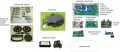
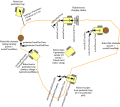
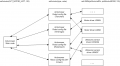
Komponenten Überblick
Chassis Komponenten
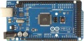
Das Hirn des Ardumowers : Der Arduino Mega 2560 Mikrocontroller
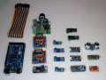
Im Shop verfügbare Module
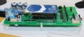
Die Ardumower LP verbindet alle Module (verfügbar im Shop)
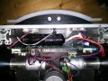
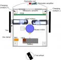
Chassis und LP im Innern
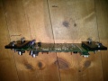
Leiterplatte montiert


Benötigte Module
Alle Module können als komplettes Kit über den shop ![]() bezogen werden .
bezogen werden .
- Hauptfunktionen
- Arduino Kabel (female-female and male-female jumper cable)
- Arduino Mega 2560 (oder Arduino Due)
- einstellbare DC voltage step-down Module (3.3v, 5v, 8v)
- zweifach Motortreiber-Modul mit integriertem Stromsensor (2 Antriebsmotoren)
- Stromsensor Module
- Motortreiber-Modul mit integriertem Stromsensor (Mähmotor)
- Widerstände, Kondensatoren, Sicherungen
- Piezo Buzzer, Taster, Ein/Aus-Schalter
- Perimeter Sender (optional)
- Arduino Nano
- DC voltage step-down Module
- Motortreiber-Modul mit integriertem Stromsensor
- Perimeter Emfpänger (optional)
- Vorverstärker-Module
- Kondensatoren, Empfängerspulen
- zusätzliche Module
- IMU module (Gyro, Beschleunigungssensor. Kompass) (erforderlich)
- Echtzeituhr (erforderlich)
- Bluetooth Module (zur Steuerung über Handy/Tablet, empfohlen)
- Ultraschall-Module(optional)
Hauptleiterplatte
Die Leiterplatte wurde mit folgenden Parametern entwickelt:
- LP Abmessungen 241x114mm
- Alle Module (Motortreiber, Bluetooth, usw.) können auf die Leiterplatte gelötet (oder gesteckt) werden (Modules sind im Ardumower-Shop verfügbar)
- Verwendet den Arduino Mega 2560
- Optional: kann der Arduino Due mittels zusätzlicher LP-Adapter verwendet werden
- Optional: integrierter Ladestromkreis (Strombegrenzung)
- alle Verbindungen, einschliesslich +5V und GND, sind über Steckverbinder realisiert
- Max. Strombelastung der Leiterbahnen (für Motoren): 8A
Leiterplattenversionen
Roboterplatine v0.5 (1. Prototyp)
Roboterplatine v1.2 (geringe Layoutänderungen)
- Schaltpläne
- Photos
- WorkaRound20150527
- WorkaRound20150530
- Motor-decrease noise REV20150531, (englische Kommentare)
Roboterplatine PCB v1.3 (in Entwicklung)
- vereinfachtes Design (Due Adapter werden extern sein)
- Motorschutzschaltung
- Batterie-Abschaltung, Sicherheitsschalter
- setzt 'Referenzdesign' und erfordert die Module: 3x DC/DC, RTC, IMU
Bemerkung: Das Schaltbild und die Platinen-Zeichnungen wurden mit KiCad entwickelt. Sie können hier heruntergeladen github und damit bearbeitet werden KiCAD software.
Leiterplatten Jumper
| Feature used | YES | NO | Comment |
|---|---|---|---|
| integrierter Laderegle mit einstellbarem
Spannungsregler (LM350T) mit Potentiomter für einstellbare Ladespannung (empfohlen: Nein) |
D7: DIODE
D3: DIODE C1, C4, U4, RV1: verwendet |
D7: brücken
D3: brücken C1, C4, U4, RV1: nicht verwendet |
Bei externem Ladegerät nicht verwenden |
| externe Stromversorgung währen des Ladens (empfohlen: Nein) | JP6: geschlossen
JP7: offen D4: DIODE C5: nicht verwendet |
JP6: offen
JP7: geschlossen D4: brücken C5: verwendet |
um Platine von aussen mit Strom zu versorgen (trennt Akku von Platine) während des Ladens |
| von Arduino gesteuertes Laderelais (empfohlen: ja) | JP4: geschlossen
JP5: offen |
JP4: offen
JP5: geschlossen |
verwendet für vom Arduino gesteuertem Laderelais (keine automatische Ladung) |
| Arduino Due (3.3V I/O) | LP0, ..., LP15: offen | LP0, ..., LP15: geschlossen | Nicht verwenden bei Arduino Mega |
| Bluetooth VCC=3.3V | JP8: offen
JP9: geschlossen |
JP8: geschlossen
JP9: offen |
viele neuere Module laufen mit 3.3V |
| Bluetooth Programmier-Modus | JP2: geschlossen | JP2: offen | verwendet für Programmierung der BAUD-Rate usw. |
Leiterplatten-Module
| Module | Feature | Pinout | Optional | Comment |
|---|---|---|---|---|
| U1 | DC/DC Wandler (10V) | GND, Vout, Vin, GND | Nein | |
| U2 | Bluetooth (HC-05) | VCC, GND, TXD, RXD, Key, LED | Ja | |
| U3 | Stromsensor (Ladestrom) | VCC, GND, OUT, IP+, IP-5 | Ja | |
| U4 | Laderegler (LM350T) | AJD, OUT, IN | Ja | |
| U5 | Stromsensor (währen des Ladens) | VCC, GND, OUT, IP+, IP-5 | Ja | |
| U6 | DC/DC Wandler (3.3V) | GND, Vout, Vin, GND | Nein | |
| U7 | DC/DC Wandler (5V) | GND, Vout, Vin, GND | Nein | |
| U8 | Echtzeituhr (DS1307) | Batt, GND, VCC, SDA, SCL, DS, SQ | Ja | |
| U9 | WLAN (ESP8266) | TX, CH_PD, Reset, VCC, GND, GP_IO2, GP_IO0, RX | Ja | |
| U10 | Pegelwandler 5V->3V (Arduino Due) | Ja | ||
| U11 | WLAN(ESP8266) | TX, CH_PD, Reset, VCC, GND, GP_IO2, GP_IO0, RX | Ja | alternative Montageposition |
Leiterplatten Steckverbinder
| Connector | Feature | Pinout | Optional | Comment |
|---|---|---|---|---|
| P1 | Sonar center (HC SR-04) | 5V, GND, Trigger, Echo | Yes | |
| P2 | Sonar right (HC SR-04) | 5V, GND, Trigger, Echo | Yes | |
| P3 | Sonar left (HC SR-04) | 5V, GND, Trigger, Echo | Yes | |
| P4 | reserved | Yes | ||
| P5 | IMU (gyro,acceleration,compass) (GY-80) | Yes | ||
| P6 | Lawn sensor | Yes | ||
| P7 | Status LEDs | Yes | ||
| P8 | Odometry right | Yes | ||
| P9 | Odometry left | Yes | ||
| P10 | GPS (GY-NEO6MV2) | Yes | ||
| P11 | Bumper | GND, GND, right, left | Yes | |
| P12 | Perimeter coil (center or left) | 5V, GND, perimeter | Yes | |
| P13 | R/C remote control | 5V, GND, mow, steer, speed, switch | Yes | |
| P14 | Measurement points | 5V, GND, (Depending on JP15: 3.3V, 5V or Arduino 3.3V) | Yes | |
| P15 | Wheel motor left | M1OUT1, M1OUT2 | No | |
| P16 | Optional motor driver input | Yes | Do not connect | |
| P17 | Optional motor driver input | Yes | Do not connect | |
| P18 | Wheel motor right | M2OUT1, M2OUT2 | No | |
| P19 | Tilt sensor | 5V, GND, tilt | Yes | |
| P20 | Button (Start/Stop) | No | ||
| P21 | Drop sensor right | Yes | ||
| P22 | Reserved | Yes | ||
| P23 | Reserved | Yes | ||
| P24 | Reserved | Yes | ||
| P25 | Reserved | Yes | ||
| P26 | Reserved | Yes | ||
| P27 | Reserved | Yes | ||
| P28 | Reserved | Yes | ||
| P29 | Reserved | Yes | ||
| P30 | Perimeter coil right | Yes | ||
| P31 | Drop sensor left | Yes | ||
| P32 | GND | Yes | ||
| P33 | 5V | Yes | ||
| P34 | 3.3V | Yes | ||
| P35 | Mower motor RPM | Yes | ||
| P36 | Reserved | Yes | ||
| P37 | Mower motor | No | ||
| P38 | Reserved | Yes | ||
| P39 | Reserved | Yes | ||
| P40 | User switches | Yes | ||
| P41 | Rain sensor | Yes | ||
| P42 | Charging pins | Yes | ||
| P43 | Battery (24V) | No | ||
| P44 | Wifi module (ESP8266) | Yes | ||
| P45 | Reserved | Yes | ||
| P46 | Reserved | Yes |
Stromversorgung
Bitte lies auch den Abschnitt 'Spannungen' unter Motor driver für mehr Informationen über die Motorspannung
Empfehlenswert ist die Verwendung von Step down Spannungswandlern (d.h. Module verwenden LM2596) um die 5V Spannung für den Arduino und alle zusätzlichen Module zu erzeugen. vor der Verbindung mit der Schaltung (Jumper), stelle den Wandler auf 5V ein, dann erst den Jumper schliessen.
![]() Warnung : niemals mehr als 5V an die Arduino 5V pins anlegen, das würde den Arduino zerstören. Deshalb, immer die 5V messen bevor die Verbindung zum 5V Pin des Arduino erfolgt!
Alle Komponenten zusammen (wie im Schaltbild gezeigt) benötigen ca. 5W Leistung.
Warnung : niemals mehr als 5V an die Arduino 5V pins anlegen, das würde den Arduino zerstören. Deshalb, immer die 5V messen bevor die Verbindung zum 5V Pin des Arduino erfolgt!
Alle Komponenten zusammen (wie im Schaltbild gezeigt) benötigen ca. 5W Leistung.
NOTE: Perimeterspule/Verstärker von DC/DC-Wandlern ferhalten (Störstrahlung)!

Download and flash Arduino code
NOTE: If you have never worked with Arduino before, read our 'Arduino first steps' introduction.
You have two options:
- Download github code (recommended) OR
- Download v0.9.3 code (old, not recommended)
Finally, download and start the Arduino IDE to flash the code to your Arduino.
Arduino Version: It is very Importent that you use the Arduino IDE version 1.6.3 or above AND select the right Board (Mega 2560 or Due).
![]() Note: Always verify that the pin configuration in your Arduino code (config.h/mower.cpp) matches your actual circuit!
Note: Always verify that the pin configuration in your Arduino code (config.h/mower.cpp) matches your actual circuit!
First-time calibration
Wheel motors
![]() Security note: For security reasons, always remove mower blades in your first tests!
Security note: For security reasons, always remove mower blades in your first tests!
Initially, you should verify that the wheel motors are controlled correctly and in the right direction. The software offers a diagnostic mode. Open the serial console in the Arduino IDE (CTRL+SHIFT+M) and set the baudrate to 19200. The motor and sensor values should appear constantly:
    20 OFF  spd    0    0    0 sen    0    0    0 bum    0    0 son...
    21 OFF  spd    0    0    0 sen    0    0    0 bum    0    0 son...
    22 OFF  spd    0    0    0 sen    0    0    0 bum    0    0 son...
    23 OFF  spd    0    0    0 sen    0    0    0 bum    0    0 son...
    24 OFF  spd    0    0    0 sen    0    0    0 bum    0    0 son...
    ...
Now, press the key ‘t’ on the keyboard, and confirm using ENTER. The diagnostic mode should appear, and you can test your motors.
ADC calibration
Run the ADC calibration once (either via serial console or "pfodApp->ADC Calibration"), so that the received signal is symmetric around zero.
Diagnostics/troubleshooting
Each time a sensor triggers, its corresponding sensor counter increases. The sensor trigger counters as well as the current sensor values can be viewed on the serial console. The following values are shown for the trigger counters in the serial console:
- Time of state machine's state (ms)
- loop()-counts per second
- choosen Verbose-Mode (0=counter readings/1=current values/2=current values)
- current state machine state (FORW, REV, ROLL etc.)
- drive home? (1/0)
- "spd" - Control/speed motors: left (PWM), right (PWM), mower (RPM)
- "sen" - Current limit exceeded counter motors: left, right, mower
- "bum" - bumper counter: left, right
- "son" - Ultrasonic-distance threshold exceeded (counter)
- "pit/roll" - Tilt (computed by acceleration sensor)
- "com" - compass course
- "per" - Perimeter loop detected: counter
- "bat" - Battery voltage
- "chg" - Charging current
Using the key 'v', you can toggle between sensor trigger counters and current sensor values.
![]() Additionally, you can use pfodApp (Android) to plot the sensors (trigger counters and current values) over time. This allows you to wirelessly monitor your robot mower for error diagnostics. It is highly recommended.
Additionally, you can use pfodApp (Android) to plot the sensors (trigger counters and current values) over time. This allows you to wirelessly monitor your robot mower for error diagnostics. It is highly recommended.
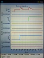
Sensor trigger counters
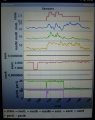
Sensor measurement values


Starting the mower
To start the mower, you need to add a button and a buzzer:
pinButton —o Button o— GND (button for ON/OFF)
pinBuzzer —o Buzzer o— GND (Piezo buzzer)
Now, press the button as long as you hear the beeps:
Mode (press button for x beeps):
1 beeps : Normal mowing (using blade modulation if available)
2 beeps : Normal mowing (without blade modulation)
3 beeps : Drive by model remote control (RC)
4 beeps : Drive without mowing
5 beeps : Find perimeter and track it
Error counter / error beeps
If there's a communication problem or another serious problem, the error counter increases. The error counter can be monitored via pfodApp. Additionally, the robot mower will beep when started.
See section Troubleshooting for details on all errors.
I2C bus / error beeps
Several components (Arduino Nano, RTC, IMU, etc.) are communicating via the I2C bus (SDA/SCL wires). These wires should be very short (maybe even twisted) and they should be far away from DC converter and motor drivers. If there's a communication problem, the error counter will increase and robot will beep when started. The error counter can be monitored via pfodApp.
Settings
The robot uses settings that you can adjust for your own robot and environment (via pfodApp or directly in the code). The default settings (factory settings) are stored in the config file 'mower.cpp'.
The settings can be adjusted via Android phone (pfodApp).
General settings
Motor speed settings
General config file idea


Important: If you uploaded a new version into your robot, reset all settings via pfodApp once (Settings->Factory reset). This will delete all existing settings. Old settings can produce malfunction if the internal settings format has changed.