Ardumower PCB: Unterschied zwischen den Versionen
(→First-time usage) |
(→First-time usage) |
||
| (41 dazwischenliegende Versionen desselben Benutzers werden nicht angezeigt) | |||
| Zeile 1: | Zeile 1: | ||
| − | + | ||
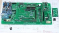
| + | [[File: Pcb_top.jpg | 800px]] | ||
| + | |||
This page describes how to assemble the Ardumower PCB, flash the Arduino and configure the robot mower. | This page describes how to assemble the Ardumower PCB, flash the Arduino and configure the robot mower. | ||
| + | |||
| + | =Abstract= | ||
The controller is built around a ready microcontroller board (Arduino Mega 2560 using 54 I/O pins). | The controller is built around a ready microcontroller board (Arduino Mega 2560 using 54 I/O pins). | ||
<gallery> | <gallery> | ||
File: Ardumower_overview.png | Components overview | File: Ardumower_overview.png | Components overview | ||
| − | |||
| − | |||
| − | |||
File: Ardumower_pcb_photo.jpg | Ardumower PCB connects all modules (available in the shop) | File: Ardumower_pcb_photo.jpg | Ardumower PCB connects all modules (available in the shop) | ||
| − | File: | + | File: Pcb_top.jpg | PCB top |
| − | File: | + | File: Pcb_bluetooth.jpg | PCB back |
| + | File: Pcb_mc33926.jpg | PCB and MC33926 | ||
</gallery> | </gallery> | ||
| Zeile 16: | Zeile 18: | ||
All modules can be purchased as complete kits via the [https://www.marotronics.de/index.php?k=7 shop] [[File: shopping.png|link=https://www.marotronics.de/index.php?k=7]] . | All modules can be purchased as complete kits via the [https://www.marotronics.de/index.php?k=7 shop] [[File: shopping.png|link=https://www.marotronics.de/index.php?k=7]] . | ||
| − | |||
| − | |||
| − | |||
| − | |||
| − | |||
| − | |||
| − | |||
| − | |||
| − | |||
| − | |||
| − | |||
| − | |||
| − | |||
| − | |||
| − | |||
| − | |||
| − | |||
| − | |||
| − | |||
| − | |||
| − | |||
| − | |||
| − | |||
| − | |||
| − | |||
| − | |||
| − | |||
| − | |||
| − | |||
| − | |||
| − | |||
| − | |||
| − | |||
| − | |||
| − | |||
| − | |||
| − | |||
| − | |||
| − | |||
| − | |||
| − | |||
| − | |||
| − | |||
| − | |||
| − | |||
| − | |||
| − | |||
| − | |||
| − | |||
| − | |||
| − | |||
| − | |||
| − | |||
| − | |||
=PCB= | =PCB= | ||
| Zeile 82: | Zeile 30: | ||
* Max. trace current (for motors): 8A | * Max. trace current (for motors): 8A | ||
| − | ==PCB | + | ==PCB building manual== |
Robot PCB v0.5 (initial prototype, please do not use anymore) | Robot PCB v0.5 (initial prototype, please do not use anymore) | ||
| − | * [https://github.com/Ardumower/ardumower/tree/master/pcb/megashield_svn_0.5/Platinenbilder Photos] | + | * [https://github.com/Ardumower/ardumower/tree/master/pcb/Produzierte_Platinen/megashield_svn_0.5/Platinenbilder Photos] |
| − | * [https://github.com/Ardumower/ardumower/raw/master/pcb/megashield_svn_0.5/ardumower%20mega%20shield%20svn.pdf Schematics] | + | * [https://github.com/Ardumower/ardumower/raw/master/pcb/Produzierte_Platinen/megashield_svn_0.5/ardumower%20mega%20shield%20svn.pdf Schematics] |
* [http://www.ardumower.de/media/kunena/attachments/1259/ArdumuverBestckung2015-04-221115.pdf Build instructions] | * [http://www.ardumower.de/media/kunena/attachments/1259/ArdumuverBestckung2015-04-221115.pdf Build instructions] | ||
* [http://www.ardumower.de/media/kunena/attachments/905/TranslatedcopyofPrototypPlatine.docx.pdf Build instructions (English translation)] | * [http://www.ardumower.de/media/kunena/attachments/905/TranslatedcopyofPrototypPlatine.docx.pdf Build instructions (English translation)] | ||
Robot PCB v1.2 (minor layout changes) | Robot PCB v1.2 (minor layout changes) | ||
| − | * [https://github.com/Ardumower/ardumower/raw/master/pcb/megashield_svn_1.2_geschlossen/ardumower%20mega%20shield%20svn.pdf Schematics] | + | * [https://github.com/Ardumower/ardumower/raw/master/pcb/Produzierte_Platinen/megashield_svn_1.2_geschlossen/ardumower%20mega%20shield%20svn.pdf Schematics] |
| − | * [https://github.com/Ardumower/ardumower/tree/master/pcb/megashield_svn_1.2_geschlossen/Platinenbilder Photos] | + | * [https://github.com/Ardumower/ardumower/tree/master/pcb/Produzierte_Platinen/megashield_svn_1.2_geschlossen/Platinenbilder Photos] |
* [http://www.ardumower.de/media/kunena/attachments/1259/ArdumuverBestckung2015-04-221115.pdf Build instructions] | * [http://www.ardumower.de/media/kunena/attachments/1259/ArdumuverBestckung2015-04-221115.pdf Build instructions] | ||
* [http://www.ardumower.de/media/kunena/attachments/905/TranslatedcopyofPrototypPlatine.docx.pdf Build instructions (English translation)] | * [http://www.ardumower.de/media/kunena/attachments/905/TranslatedcopyofPrototypPlatine.docx.pdf Build instructions (English translation)] | ||
| − | * [https://github.com/Ardumower/ardumower/ | + | * [https://github.com/Ardumower/ardumower/blob/master/Dokumentation/Megashield%20svn%201.2%20und%20V0.5/WorkaRound20150527.pdf WorkaRound20150527] |
| − | * [https://github.com/Ardumower/ardumower/ | + | * [https://github.com/Ardumower/ardumower/blob/master/Dokumentation/Megashield%20svn%201.2%20und%20V0.5/WorkaRound20150530.pdf WorkaRound20150530] |
| − | * | + | * also see: Documentation in [https://github.com/Ardumower/ardumower/tree/master/Dokumentation Github] |
| − | + | ||
| − | |||
| − | |||
| − | |||
| − | |||
'''NOTE:''' The schematics and PCB files were created with KiCad. They can be downloaded from [https://github.com/Ardumower/ardumower/archive/master.zip github] and can be edited by open source KiCAD software (Download [https://docs.google.com/uc?id=0BzTsqkQk2FRsSEhOR2tVc1p4LVk&export=download here] or [http://iut-tice.ujf-grenoble.fr/cao/KiCad_stable-2013.07.07-BZR4022_Win_full_version.exe here]). | '''NOTE:''' The schematics and PCB files were created with KiCad. They can be downloaded from [https://github.com/Ardumower/ardumower/archive/master.zip github] and can be edited by open source KiCAD software (Download [https://docs.google.com/uc?id=0BzTsqkQk2FRsSEhOR2tVc1p4LVk&export=download here] or [http://iut-tice.ujf-grenoble.fr/cao/KiCad_stable-2013.07.07-BZR4022_Win_full_version.exe here]). | ||
| + | |||
| + | ==PCB building videos== | ||
| + | * [https://www.youtube.com/watch?feature=player_embedded&v=smZj60sxQvU Resistors] | ||
| + | * [https://www.youtube.com/watch?feature=player_embedded&v=chEBCcJDsjg Diodes and relay] | ||
| + | * [https://www.youtube.com/watch?feature=player_embedded&v=O6nyuSsCH1I Capacitors and transistors] | ||
| + | * [https://www.youtube.com/watch?feature=player_embedded&v=m8XGWGwdEBk Piezo buzzer and fuse] | ||
| + | * [https://www.youtube.com/watch?feature=player_embedded&v=a1y8C_uRdtA Strip pins] | ||
| + | * [https://www.youtube.com/watch?feature=player_embedded&v=RrU6lTCU0cc DC/DC converter] | ||
| + | * [https://www.youtube.com/watch?feature=player_embedded&v=fOvV-kD0y7k RTC module] | ||
| + | * [https://www.youtube.com/watch?feature=player_embedded&v=DokrJiVzX2I Dual MC33926] | ||
| + | * [https://www.youtube.com/watch?feature=player_embedded&v=lyCH8CQD358 INA169] | ||
| + | * [https://www.youtube.com/watch?feature=player_embedded&v=M-rC03VlGK4 Battery & charger] | ||
==PCB jumpers== | ==PCB jumpers== | ||
| Zeile 180: | Zeile 135: | ||
==PCB modules== | ==PCB modules== | ||
| + | |||
| + | [[Image:Ina169_marotronics.jpg|thumb|200px| Note for Marotronics INA169: Short pads for 5A operation]] | ||
{| class="wikitable" | {| class="wikitable" | ||
| Zeile 550: | Zeile 507: | ||
[[File:warning.png]]Warning : never connect more than 5V on the Arduino 5V pins, or you will damage the Arduino. Therefore, always measure the 5V voltage before connecting it to the Arduino 5V pin! | [[File:warning.png]]Warning : never connect more than 5V on the Arduino 5V pins, or you will damage the Arduino. Therefore, always measure the 5V voltage before connecting it to the Arduino 5V pin! | ||
All components together (as shown in the schematics) need about 5W power. | All components together (as shown in the schematics) need about 5W power. | ||
| − | |||
| − | |||
| − | |||
| − | |||
=Download and flash Arduino code= | =Download and flash Arduino code= | ||
| Zeile 567: | Zeile 520: | ||
'''Arduino Version''': It is very Importent that you use the Arduino IDE version 1.6.3 or above AND select the right Board (Mega 2560 or Due). | '''Arduino Version''': It is very Importent that you use the Arduino IDE version 1.6.3 or above AND select the right Board (Mega 2560 or Due). | ||
| − | [[File:warning.png]] Important for Arduino IDE 1.6 or higher: if you see any folders inside the code folder (e.g. 'unused'), please delete them before compilation! | + | [[File:warning.png]] <b>Important for Arduino IDE 1.6 or higher: if you see any folders inside the code folder (e.g. 'unused'), please delete them before compilation! </b> Note: Always verify that the pin configuration in your Arduino code (config.h/mower.cpp) matches your actual circuit! |
| + | |||
| + | =Settings= | ||
| + | The robot uses settings that you can adjust for your own robot and environment (via pfodApp or directly in the code). The default settings (factory settings) are stored in the config file 'mower.cpp'. In this file you can find a description of all settings. | ||
| + | |||
| + | The settings can be adjusted via Android phone ([http://wiki.ardumower.de/index.php?title=Bluetooth pfodApp]). | ||
| + | |||
| + | <gallery> | ||
| + | File:Cheat_sheet.png | Visualization of settings | ||
| + | File:Speedcontrol.png | Motor speed settings | ||
| + | </gallery> | ||
| + | |||
| + | Important: If you uploaded a new version into your robot, reset all settings via pfodApp once (Settings->Factory reset). This will delete all existing settings. Old settings can produce malfunction if the internal settings format has changed. | ||
=First-time usage= | =First-time usage= | ||
| − | 1. | + | 1. At first, deactivate all sensors - In 'mower.cpp' set the robot settings like this: |
| − | + | ||
bumperUse = 0; | bumperUse = 0; | ||
dropUse = 0; | dropUse = 0; | ||
| Zeile 586: | Zeile 551: | ||
timerUse = 0; | timerUse = 0; | ||
| − | 2. The software offers a serial console mode. Open the serial console in the Arduino IDE (CTRL+SHIFT+M) and set the baudrate to 19200. The motor and sensor values should appear constantly. First let's delete any existing error | + | 2. The software offers a serial console mode. Open the serial console in the Arduino IDE (CTRL+SHIFT+M) and set the baudrate to 19200. The motor and sensor values should appear constantly. First let's delete any existing error. Send the letter 'd' to the Arduino. |
Console: | Console: | ||
| Zeile 594: | Zeile 559: | ||
3. Run the ADC calibration, so that the ADC signals are symmetric around zero. | 3. Run the ADC calibration, so that the ADC signals are symmetric around zero. | ||
| + | pres... | ||
| + | 8=ADC calib (perimeter sender, charger must be off) | ||
| + | 4. Save user settings | ||
press... | press... | ||
| − | + | 9=saver user settings | |
| − | + | ||
| − | + | 5. Test motors: | |
| − | + | ||
press... | press... | ||
| − | |||
1=test motors | 1=test motors | ||
| Zeile 608: | Zeile 573: | ||
You should verify that the wheel motors are controlled correctly and in the right direction. Increase 'motorAccel' in 'mega.cpp' if the motors are not accelerating quickly enough. | You should verify that the wheel motors are controlled correctly and in the right direction. Increase 'motorAccel' in 'mega.cpp' if the motors are not accelerating quickly enough. | ||
| + | |||
| + | =Starting the mower= | ||
| + | |||
| + | To start the mower, you need to add a button and a buzzer: | ||
| + | |||
| + | pinButton —o Button o— GND (button for ON/OFF) | ||
| + | |||
| + | pinBuzzer —o Buzzer o— GND (Piezo buzzer) | ||
| + | |||
| + | Now, press the button as long as you hear the beeps: | ||
| + | |||
| + | Mode (press button for x beeps): | ||
| + | 1 beeps : Normal mowing (using blade modulation if available) | ||
| + | 2 beeps : Normal mowing (without blade modulation) | ||
| + | 3 beeps : Drive by model remote control (RC) | ||
| + | 4 beeps : Drive without mowing | ||
| + | 5 beeps : Find perimeter and track it | ||
=Diagnostics/troubleshooting= | =Diagnostics/troubleshooting= | ||
| Zeile 634: | Zeile 616: | ||
File:Ardumower_sensor_counter_plotting.jpg |Sensor trigger counters | File:Ardumower_sensor_counter_plotting.jpg |Sensor trigger counters | ||
File:Ardumower_plot_sensors.jpg |Sensor measurement values | File:Ardumower_plot_sensors.jpg |Sensor measurement values | ||
| + | File: Ardumower_states.png | Ardumower states | ||
</gallery> | </gallery> | ||
| − | = | + | ==Error codes and troubleshooting== |
| − | + | http://wiki.ardumower.de/index.php?title=Troubleshooting | |
| − | + | ||
| − | + | ||
| − | + | ||
| − | + | ||
| − | + | ||
| − | + | ||
| − | + | ||
| − | + | ||
| − | + | ||
| − | + | ||
| − | + | ||
| − | + | ||
| − | + | ||
| − | + | ||
=Error counter / error beeps= | =Error counter / error beeps= | ||
| Zeile 660: | Zeile 629: | ||
==I2C bus / error beeps== | ==I2C bus / error beeps== | ||
Several components (Arduino Nano, RTC, IMU, etc.) are communicating via the I2C bus (SDA/SCL wires). These wires should be very short (maybe even twisted) and they should be far away from DC converter and motor drivers. If there's a communication problem, the error counter will increase and robot will beep when started. The error counter can be monitored via pfodApp. | Several components (Arduino Nano, RTC, IMU, etc.) are communicating via the I2C bus (SDA/SCL wires). These wires should be very short (maybe even twisted) and they should be far away from DC converter and motor drivers. If there's a communication problem, the error counter will increase and robot will beep when started. The error counter can be monitored via pfodApp. | ||
| − | |||
| − | |||
| − | |||
| − | |||
| − | |||
| − | |||
| − | |||
| − | |||
| − | |||
| − | |||
| − | |||
| − | |||
| − | |||
=Further links= | =Further links= | ||
Aktuelle Version vom 1. April 2017, 08:14 Uhr

This page describes how to assemble the Ardumower PCB, flash the Arduino and configure the robot mower.
Inhaltsverzeichnis
Abstract
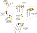
The controller is built around a ready microcontroller board (Arduino Mega 2560 using 54 I/O pins).
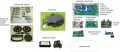
Components overview
Ardumower PCB connects all modules (available in the shop)
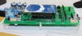
PCB top
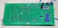
PCB back
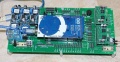
PCB and MC33926


Needed modules
All modules can be purchased as complete kits via the shop ![]() .
.
PCB
The printed circuit board (PCB) connects all electronic modules. The PCB is made with the following design parameters:
- PCB dimensions 241x114mm
- All modules (motor driver, Bluetooth, etc.) can be soldered (or plugged) on the PCB (modules are available in the Ardumower shop)
- Uses the Arduino Mega 2560
- Optional: can use Arduino Due via additional adapter PCB
- Optional: integrated charging circuit (current limiting)
- All connections are available on connectors as well as +5V and GND
- Max. trace current (for motors): 8A
PCB building manual
Robot PCB v0.5 (initial prototype, please do not use anymore)
Robot PCB v1.2 (minor layout changes)
- Schematics
- Photos
- Build instructions
- Build instructions (English translation)
- WorkaRound20150527
- WorkaRound20150530
- also see: Documentation in Github
NOTE: The schematics and PCB files were created with KiCad. They can be downloaded from github and can be edited by open source KiCAD software (Download here or here).
PCB building videos
- Resistors
- Diodes and relay
- Capacitors and transistors
- Piezo buzzer and fuse
- Strip pins
- DC/DC converter
- RTC module
- Dual MC33926
- INA169
- Battery & charger
PCB jumpers
| Feature used | YES | NO | Comment |
|---|---|---|---|
| Integrated charging control via adjustable
voltage regulator (LM350T) with potentiometer for adjustable charging voltage (recommended: NO) |
D7: DIODE
D3: DIODE C1, C4, U4, RV1: used |
D7: SHORT-CIRCUIT
D3: SHORT-CIRCUIT C1, C4, U4, RV1: not used |
Do not use if using external battery charger |
| External power while charging (recommended: NO) | JP6: CLOSE
JP7: OPEN D4: DIODE C5: not used |
JP6: OPEN
JP7: CLOSE D4: SHORT-CIRCUIT C5: used |
Use to power your PCB from externally (disconnect battery from PCB) while charging |
| Arduino controlled charge relay (recommended: YES) | JP4: CLOSE
JP5: OPEN |
JP4: OPEN
JP5: CLOSE |
Use for Arduino controlled charge relay (not automatic charging) |
| Arduino Due (3.3V I/O) | LP0, ..., LP15: OPEN | LP0, ..., LP15: CLOSE | Do not use if using Arduino Mega |
| Bluetooth VCC=3.3V | JP8: OPEN
JP9: CLOSE |
JP8: CLOSE
JP9: OPEN |
Many latest modules use 3.3V |
| Bluetooth programming mode | JP2: CLOSE | JP2: OPEN | Use for reprogramming baud rate etc. |
PCB modules

| Module | Feature | Pinout | Optional | Comment |
|---|---|---|---|---|
| U1 | DC/DC converter (10V) | GND, Vout, Vin, GND | No | |
| U2 | Bluetooth (HC-05) | VCC, GND, TXD, RXD, Key, LED | Yes | |
| U3 | Current sensor (charging) | VCC, GND, OUT, IP+, IP-5 | Yes | |
| U4 | Charge control (LM350T) | AJD, OUT, IN | Yes | |
| U5 | Current sensor (charging) | VCC, GND, OUT, IP+, IP-5 | Yes | |
| U6 | DC/DC converter (3.3V) | GND, Vout, Vin, GND | No | |
| U7 | DC/DC converter (5V) | GND, Vout, Vin, GND | No | |
| U8 | Realtime clock (DS1307) | Batt, GND, VCC, SDA, SCL, DS, SQ | Yes | |
| U9 | Wifi (ESP8266) | TX, CH_PD, Reset, VCC, GND, GP_IO2, GP_IO0, RX | Yes | |
| U10 | Level shifter 5V->3V (Arduino Due) | Yes | ||
| U11 | Wifi (ESP8266) | TX, CH_PD, Reset, VCC, GND, GP_IO2, GP_IO0, RX | Yes | alternative mount position |
PCB connectors
| Connector | Feature | Pinout | Optional | Comment |
|---|---|---|---|---|
| P1 | Sonar center (HC SR-04) | 5V, GND, Trigger, Echo | Yes | |
| P2 | Sonar right (HC SR-04) | 5V, GND, Trigger, Echo | Yes | |
| P3 | Sonar left (HC SR-04) | 5V, GND, Trigger, Echo | Yes | |
| P4 | reserved | Yes | ||
| P5 | IMU (gyro,acceleration,compass) (GY-80) | Yes | ||
| P6 | Lawn sensor | Yes | ||
| P7 | Status LEDs | Yes | ||
| P8 | Odometry right | Yes | ||
| P9 | Odometry left | Yes | ||
| P10 | GPS (GY-NEO6MV2) | Yes | ||
| P11 | Bumper | GND, GND, right, left | Yes | |
| P12 | Perimeter coil (center or left) | 5V, GND, perimeter | Yes | |
| P13 | R/C remote control | 5V, GND, mow, steer, speed, switch | Yes | |
| P14 | Measurement points | 5V, GND, (Depending on JP15: 3.3V, 5V or Arduino 3.3V) | Yes | |
| P15 | Wheel motor left | M1OUT1, M1OUT2 | No | |
| P16 | Optional motor driver input | Yes | Do not connect | |
| P17 | Optional motor driver input | Yes | Do not connect | |
| P18 | Wheel motor right | M2OUT1, M2OUT2 | No | |
| P19 | Tilt sensor | 5V, GND, tilt | Yes | |
| P20 | Button (Start/Stop) | No | ||
| P21 | Drop sensor right | Yes | ||
| P22 | Reserved | Yes | ||
| P23 | Reserved | Yes | ||
| P24 | Reserved | Yes | ||
| P25 | Reserved | Yes | ||
| P26 | Reserved | Yes | ||
| P27 | Reserved | Yes | ||
| P28 | Reserved | Yes | ||
| P29 | Reserved | Yes | ||
| P30 | Perimeter coil right | Yes | ||
| P31 | Drop sensor left | Yes | ||
| P32 | GND | Yes | ||
| P33 | 5V | Yes | ||
| P34 | 3.3V | Yes | ||
| P35 | Mower motor RPM | Yes | ||
| P36 | Reserved | Yes | ||
| P37 | Mower motor | No | ||
| P38 | Reserved | Yes | ||
| P39 | Reserved | Yes | ||
| P40 | User switches | Yes | ||
| P41 | Rain sensor | Yes | ||
| P42 | Charging pins | Yes | ||
| P43 | Battery (24V) | No | ||
| P44 | Wifi module (ESP8266) | Yes | ||
| P45 | Reserved | Yes | ||
| P46 | Reserved | Yes |
Power supply
Please also read the section 'Voltages' under Motor driver for more information on motor voltages.
It is recommended to use a voltage step-down converter (e.g. module using LM2596) to generate the 5V voltage for the Arduino and all additional modules. Before connecting, set the voltage of the converter to 5V.
![]() Warning : never connect more than 5V on the Arduino 5V pins, or you will damage the Arduino. Therefore, always measure the 5V voltage before connecting it to the Arduino 5V pin!
All components together (as shown in the schematics) need about 5W power.
Warning : never connect more than 5V on the Arduino 5V pins, or you will damage the Arduino. Therefore, always measure the 5V voltage before connecting it to the Arduino 5V pin!
All components together (as shown in the schematics) need about 5W power.
Download and flash Arduino code
NOTE: If you have never worked with Arduino before, read our 'Arduino first steps' introduction.
You have two options:
- Download github code (recommended) OR
- Download v0.9.3 code (old, not recommended)
Finally, download and start the Arduino IDE to flash the code to your Arduino.
Arduino Version: It is very Importent that you use the Arduino IDE version 1.6.3 or above AND select the right Board (Mega 2560 or Due).
![]() Important for Arduino IDE 1.6 or higher: if you see any folders inside the code folder (e.g. 'unused'), please delete them before compilation! Note: Always verify that the pin configuration in your Arduino code (config.h/mower.cpp) matches your actual circuit!
Important for Arduino IDE 1.6 or higher: if you see any folders inside the code folder (e.g. 'unused'), please delete them before compilation! Note: Always verify that the pin configuration in your Arduino code (config.h/mower.cpp) matches your actual circuit!
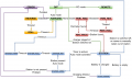
Settings
The robot uses settings that you can adjust for your own robot and environment (via pfodApp or directly in the code). The default settings (factory settings) are stored in the config file 'mower.cpp'. In this file you can find a description of all settings.
The settings can be adjusted via Android phone (pfodApp).
Visualization of settings
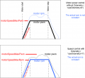
Motor speed settings


Important: If you uploaded a new version into your robot, reset all settings via pfodApp once (Settings->Factory reset). This will delete all existing settings. Old settings can produce malfunction if the internal settings format has changed.
First-time usage
1. At first, deactivate all sensors - In 'mower.cpp' set the robot settings like this:
bumperUse = 0;
dropUse = 0;
rainUse = 0;
sonarUse = 0;
perimeterUse = 0;
lawnSensorUse = 0;
imuUse = 0;
batMonitor = 0;
odometryUse = 0;
gpsUse = 0;
buttonUse = 1;
timerUse = 0;
2. The software offers a serial console mode. Open the serial console in the Arduino IDE (CTRL+SHIFT+M) and set the baudrate to 19200. The motor and sensor values should appear constantly. First let's delete any existing error. Send the letter 'd' to the Arduino.
Console:
press...
d for menu
e=delete all errors
3. Run the ADC calibration, so that the ADC signals are symmetric around zero.
pres...
8=ADC calib (perimeter sender, charger must be off)
4. Save user settings
press...
9=saver user settings
5. Test motors:
press...
1=test motors

Security note: For security reasons, always remove mower blades in your first tests!
You should verify that the wheel motors are controlled correctly and in the right direction. Increase 'motorAccel' in 'mega.cpp' if the motors are not accelerating quickly enough.
Starting the mower
To start the mower, you need to add a button and a buzzer:
pinButton —o Button o— GND (button for ON/OFF)
pinBuzzer —o Buzzer o— GND (Piezo buzzer)
Now, press the button as long as you hear the beeps:
Mode (press button for x beeps):
1 beeps : Normal mowing (using blade modulation if available)
2 beeps : Normal mowing (without blade modulation)
3 beeps : Drive by model remote control (RC)
4 beeps : Drive without mowing
5 beeps : Find perimeter and track it
Diagnostics/troubleshooting
Each time a sensor triggers, its corresponding sensor counter increases. The sensor trigger counters as well as the current sensor values can be viewed on the serial console. The following values are shown for the trigger counters in the serial console:
- Time of state machine's state (ms)
- loop()-counts per second
- choosen Verbose-Mode (0=counter readings/1=current values/2=current values)
- current state machine state (FORW, REV, ROLL etc.)
- drive home? (1/0)
- "spd" - Control/speed motors: left (PWM), right (PWM), mower (RPM)
- "sen" - Current limit exceeded counter motors: left, right, mower
- "bum" - bumper counter: left, right
- "son" - Ultrasonic-distance threshold exceeded (counter)
- "pit/roll" - Tilt (computed by acceleration sensor)
- "com" - compass course
- "per" - Perimeter loop detected: counter
- "bat" - Battery voltage
- "chg" - Charging current
Using the key 'v', you can toggle between sensor trigger counters and current sensor values.
![]() Additionally, you can use pfodApp (Android) to plot the sensors (trigger counters and current values) over time. This allows you to wirelessly monitor your robot mower for error diagnostics. It is highly recommended.
Additionally, you can use pfodApp (Android) to plot the sensors (trigger counters and current values) over time. This allows you to wirelessly monitor your robot mower for error diagnostics. It is highly recommended.
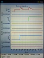
Sensor trigger counters
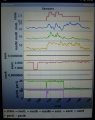
Sensor measurement values
Ardumower states


Error codes and troubleshooting
http://wiki.ardumower.de/index.php?title=Troubleshooting
Error counter / error beeps
If there's a communication problem or another serious problem, the error counter increases. The error counter can be monitored via pfodApp. Additionally, the robot mower will beep when started.
See section Troubleshooting for details on all errors.
I2C bus / error beeps
Several components (Arduino Nano, RTC, IMU, etc.) are communicating via the I2C bus (SDA/SCL wires). These wires should be very short (maybe even twisted) and they should be far away from DC converter and motor drivers. If there's a communication problem, the error counter will increase and robot will beep when started. The error counter can be monitored via pfodApp.