Azurit Firmware (English): Unterschied zwischen den Versionen
(→Error codes and troubleshooting) |
(→Error counter / error beeps) |
||
| Zeile 194: | Zeile 194: | ||
File: Ardumower_states.png | Ardumower states | File: Ardumower_states.png | Ardumower states | ||
</gallery> | </gallery> | ||
| − | |||
| − | |||
| − | |||
| − | |||
| − | |||
| − | |||
| − | |||
| − | |||
| − | |||
=Troubleshooting= | =Troubleshooting= | ||
Version vom 2. Juli 2017, 12:45 Uhr
Inhaltsverzeichnis
Download and flash Arduino code
NOTE: If you have never worked with Arduino before, read our 'Arduino first steps' introduction.
You have two options:
- Download github code (recommended) OR
- Download v0.9.3 code (old, not recommended)
Finally, download and start the Arduino IDE to flash the code to your Arduino.
Arduino Version: It is very Importent that you use the Arduino IDE version 1.6.3 or above AND select the right Board (Mega 2560 or Due).
![]() Important for Arduino IDE 1.6 or higher: if you see any folders inside the code folder (e.g. 'unused'), please delete them before compilation! Note: Always verify that the pin configuration in your Arduino code (config.h/mower.cpp) matches your actual circuit!
Important for Arduino IDE 1.6 or higher: if you see any folders inside the code folder (e.g. 'unused'), please delete them before compilation! Note: Always verify that the pin configuration in your Arduino code (config.h/mower.cpp) matches your actual circuit!
Settings
The robot uses settings that you can adjust for your own robot and environment (via pfodApp or directly in the code). The default settings (factory settings) are stored in the config file 'mower.cpp'. In this file you can find a description of all settings.
The settings can be adjusted via Android phone (pfodApp).
Visualization of settings
Motor speed settings


Important: If you uploaded a new version into your robot, reset all settings via pfodApp once (Settings->Factory reset). This will delete all existing settings. Old settings can produce malfunction if the internal settings format has changed.
First-time usage
1. At first, deactivate all sensors - In 'mower.cpp' set the robot settings like this:
bumperUse = 0;
dropUse = 0;
rainUse = 0;
sonarUse = 0;
perimeterUse = 0;
lawnSensorUse = 0;
imuUse = 0;
batMonitor = 0;
odometryUse = 0;
gpsUse = 0;
buttonUse = 1;
timerUse = 0;
2. The software offers a serial console mode. Open the serial console in the Arduino IDE (CTRL+SHIFT+M) and set the baudrate to 19200. The motor and sensor values should appear constantly. First let's delete any existing error. Send the letter 'd' to the Arduino.
Console:
press...
d for menu
e=delete all errors
3. Run the ADC calibration, so that the ADC signals are symmetric around zero.
pres...
8=ADC calib (perimeter sender, charger must be off)
4. Save user settings
press...
9=saver user settings
5. Test motors:
press...
1=test motors

Security note: For security reasons, always remove mower blades in your first tests!
You should verify that the wheel motors are controlled correctly and in the right direction. Increase 'motorAccel' in 'mega.cpp' if the motors are not accelerating quickly enough.
Starting the mower
To start the mower, you need to add a button and a buzzer:
pinButton —o Button o— GND (button for ON/OFF)
pinBuzzer —o Buzzer o— GND (Piezo buzzer)
Now, press the button as long as you hear the beeps:
Mode (press button for x beeps):
1 beeps : Normal mowing (using blade modulation if available)
2 beeps : Normal mowing (without blade modulation)
3 beeps : Drive by model remote control (RC)
4 beeps : Drive without mowing
5 beeps : Find perimeter and track it
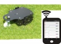
Bluetooth module

The Ardumower can be monitored and controlled wirelessly:
- via phone/tablet (Android App)
- via USB Bluetooth dongle (PC serial console)
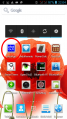
On the phone, you'll need the App 'ArduRemote'. Alternatively, you can use the App 'pfodApp'.
The phone menu includes:
- Status information (battery voltage, charging current etc.)
- Settings (Timer etc.)
- Calibration (Motor, IMU etc.)
- Remote control (Start/Stop, Switching on/off mower motor, blade modulation etc.)

Live configuration, monitoring and debugging
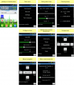
Android app menus

Android app (pfodApp)

Android app (ArduRemote)
PC communication via Bluetooth USB dongle


Bluetooth module
On the robot, you'll need a Bluetooth HC-05 module supporting Bluetooth Serial Port Profile (SPP). SPP uses Bluetooth Service Discovery Protocol (SDP) and the RFCOMM protocol.
Bluetooth HC-05
For Programming the Module, you must connect the Key Pin from the BT Module to the 3.3 V from the PCB and disconnect after programming.
Bluetooth module configuration steps
- Configuration mode: The Bluetooth module must be in configuration mode for the next step:
- for HC05: Connect KEY pin to 3.3V after powering on the module
- for HC06/linvor: Do NOT pair/connect (LED must be blinking)
- for FBT06/MBTV4: First you have to solder the PIO11 pin to VCC (PIN 12) which is 3.3 Volts using a thin wire.
- Baud rate: Blueooth module and Arduino Mega must use the same baud rate (19200) - The baud rate of the BT module can be changed via Ardumower serial console. Connect Ardumower Mega board to your PC (USB), enter the serial console in the Arduino IDE (CTRL+M), and choose baud rate 19200, then choose 'd' to enter the Ardumower menu, '3' for communications menu, and '3' to configure the module to the correct baud rate.
- Restart: After your BT module is configured successfully, remove KEY pin connection again (HC05), and restart module.
- Pairing: The BT module must be 'paired' with your Android device once (via Android device settings). On the Android device, choose symbol "Settings" (via Android menu). Now choose "Wirless and Networks->Bluetooth Settings" and "Find device". Finally, choose "pair with this device" and enter your pin (very often "1234"). The Bluetooth module should now appear as "paired".
- pfodApp: Now you can start pfodApp/ArduRemote to connect to the Ardumower.
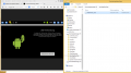
PC/Mac remote control application
In addition to the Android App, we have developed a remote control application for PC/Mac/Linux (developed in Processing/Java). The Mac standalone version has to be created within Processing, the Windows version is already available as standalone version:
- Download Windows 64 bit executable and extract it:
https://drive.google.com/uc?export=download&confirm=EYiA&id=0B90Bcwohn5_HRFFMUUFYWF9OdW8
- Download and install Java runtime (version 8 or higher): https://java.com/de/download/
- Plug-in an USB bluetooth dongle on your PC
- In Windows, pair the USB bluetooth dongle with the Ardumower bluetooth module - two new serial ports will be created on your PC (the first for incoming bluetooth connections, the 2nd one for outgoing bluetoth connections)
- Run 'processing_remote.exe', all available serial ports will be shown - select the serial port for outgoing connections
The code for Processing can be found here: https://github.com/Ardumower/ardumower/tree/master/code/Test_und_Entwicklung/processing_remote
Processing can be downloaded here: https://processing.org/
Communication protocol
You can log the communication to a file (folder 'pfodAppRawData' or 'ArduRemote') on your Android device. For the ArduRemote, press the 'Android menu button' on your device and choose 'Enable logging'.
Android menu button

Sensor logging
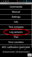
For PC data analysis, algorithm modelling and optimization, you can collect robot sensor data using pfodApp like this:
- Using your Android pfodApp, connect to your robot and choose 'Log sensors'. The logged sensor data will be displayed. Click 'Back' to stop logging (NOTE: for ArduRemote, press Android menu button before and choose 'Enable logging' to enable file logging).
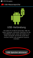
- Connect your Android phone to the PC, if being asked on the phone choose 'Enable as USB device', so you phone shows as a new Windows drive on your PC.
- On your PC, launch Windows Explorer and choose the new Android drive, browse to the 'pfodAppRawData' folder (for ArduRemote: 'ArduRemote' folder), and copy the data file to your PC (you can identify files by their Bluetooth name and date).
1. Start pfodApp
2. Choose 'Log sensors'
3. Choose phone back button or 'Exit'
4. Connect to your PC via USB, choose 'Enable as USB device'
5. Using Windows explorer, browse to folder 'pfodAppRawData' on external Android drive to access sensor log file


Videos
Diagnostics/troubleshooting
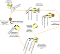
Each time a sensor triggers, its corresponding sensor counter increases. The sensor trigger counters as well as the current sensor values can be viewed on the serial console. The following values are shown for the trigger counters in the serial console:
- Time of state machine's state (ms)
- loop()-counts per second
- choosen Verbose-Mode (0=counter readings/1=current values/2=current values)
- current state machine state (FORW, REV, ROLL etc.)
- drive home? (1/0)
- "spd" - Control/speed motors: left (PWM), right (PWM), mower (RPM)
- "sen" - Current limit exceeded counter motors: left, right, mower
- "bum" - bumper counter: left, right
- "son" - Ultrasonic-distance threshold exceeded (counter)
- "pit/roll" - Tilt (computed by acceleration sensor)
- "com" - compass course
- "per" - Perimeter loop detected: counter
- "bat" - Battery voltage
- "chg" - Charging current
Using the key 'v', you can toggle between sensor trigger counters and current sensor values.
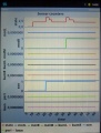
![]() Additionally, you can use pfodApp (Android) to plot the sensors (trigger counters and current values) over time. This allows you to wirelessly monitor your robot mower for error diagnostics. It is highly recommended.
Additionally, you can use pfodApp (Android) to plot the sensors (trigger counters and current values) over time. This allows you to wirelessly monitor your robot mower for error diagnostics. It is highly recommended.
Sensor trigger counters
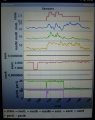
Sensor measurement values
Ardumower states


Troubleshooting
Hardware measurements
For detecting failures in the assembly or electronic parts, it is highly recommended to use an oscillscope (e.g. pocket oscillscope DSO201) for your measurements. An Oscilloscope allows you to detect short-time failures in power signals, perimeter sender and receiver signals, odometry signals and more.

Tutorial for pocket oscilloscopes: http://www.ardumower.de/index.php/de/forum/anleitungen-hilfe/142-bedienung-oszilloskop-dso201
Error codes
If your robot beeps periodically, it is in ERROR state. Either run the serial console or 'pfodApp->Error Counters' to find out the detailed error. The possible solutions for each error are given below. For details about your robot settings, see Settings.
 ERR_CPU_SPEED           CPU speed error
                         * Check I2C cables (e.g. reduce wire length)
 ERR_MOTOR_LEFT          Left gear motor error
                         * Check gear motor driver module and left gear motor (supply voltage, signal lines)
                         * MC33926: ensure SLEW jumper is not set
                         * Tracking: reduce Motor-Max-PWM and Tracking-P to reduce EMF
 ERR_MOTOR_RIGHT         Right gear motor error
                         * Check gear motor driver module and right gear motor (supply voltage, signal lines)
                         * MC33926: ensure SLEW jumper is not set
                         * Tracking: reduce Motor-Max-PWM and Tracking-P to reduce EMF
 ERR_MOTOR_MOW           Mower motor error
                         * Check mower motor driver module and mower motor (supply voltage, signal lines)
                         * MC33926: ensure SLEW jumper is not set
                         * Reduce Motor-Max-Power, so over-current is detected earlier
 ERR_MOW_SENSE           Mower motor over-current
                         * Check mower motor driver module and mower motor
                         * Increase Motor-Max-Power, so over-current is detected later
 ERR_IMU_COMM            IMU communication error
                         * Check IMU module connections
 ERR_IMU_CALIB           IMU calibration error
                         * Start IMU calibration (either via Console or pfodApp->Settings->IMU)
 ERR_IMU_TILT            IMU tilt error
                         * Check IMU module and robot orientation
 ERR_RTC_COMM            RTC communication error
                         * Check RTC module connections, RTC battery etc.
 ERR_RTC_DATA            RTC corrupt data error
                         * Set and save RTC date and time
 ERR_PERIMETER_TIMEOUT   Perimeter signal timeout
                         * Check perimeter sender, wire etc.
                         * Check coil polarity
                         * Reduce Perimeter-smag, so timeout is higher
                         * Increase Perimeter-timeout-seconds, so timeout is higher
                         * Check your signal-to-noise ratio is higher than 1.0
 ERR_TRACKING            Perimeter tracking error
                         * Check perimeter sender, wire etc.
                         * Increase Perimeter-tracking-timeout, so timeout is higher
 ERR_ODOMETRY_LEFT       Left motor odometry error
                         * Check left odometry cable
                         * Check left motor direction
 ERR_ODOMETRY_RIGHT      Right motor odometry error
                         * Check right odometry cable
                         * Check right motor direction
 ERR_BATTERY             Battery error
                         * Check battery connections
 ERR_CHARGER             Charger error
                         * Check charger connections
 ERR_GPS_COMM            GPS communication error
                         * Check GPS cables
 ERR_GPS_DATA            GPS data error
                         * Check GPS antenna and cable
 ERR_ADC_CALIB           ADC calibration error
                         * Start ADC calibration (either via Console or pfodApp->ADC calibration)
 ERR_EEPROM_DATA         EEPROM data error
                         * Save user settings (either via Console or pfodApp->Settings-Save)
After fixing the error, you can delete errors:
Console:
press...
d for menu
e=delete all errors
I2C errors
Ensure the I2C bus is working correctly. A console stucked at line 'initL3G4200D' indicates I2C is not working correctly.
Disable all pins not connected
Ensure that you have disabled all features and pins in the robot configuration that are not connected (not used).
Example: If you do not have connected odometry pins, disable them in the robot config (robot.cpp):
odometryUse = 0; // use odometry?
Motors working correctly
Run the serial console (Arduino IDE: CTRL+SHIFT+M, 19200 Baud) and press 'd' and ENTER for menu. Then press '1' and ENTER to run the motor test.
Any unexpected sensor triggering
If your robot does something unexpected, it might be a sensor that is incorrectly triggering. Check this via the serial console:
Run the serial console (Arduino IDE: CTRL+SHIFT+M, 19200 Baud), and start the robot. Each time a sensor triggers, the counter of that sensor will increase. See description of each sensor below. Now when your robot does something unexpected, have a look which of the sensor counters increased to locate the problem.
Some sensor not triggering?
...
Bluetooth not connecting?
- Verify that BT module baudrate is configured properly (using Ardumower Console) - activate programming button on BT module for programming procedure.
- Verify that BT module is 'paired' on your Android phone
- Verify that Arduino Mega is not powered via USB (but DC/DC instead)
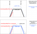
Robot not stopping to rotate when reaching perimeter (home mode)
At first, verify that the perimeter tracking itself is working: Manually put the robot on the perimeter wire, and via ArduRemote App, choose 'Commands->Track' and verify the robot is tracking the perimeter. If it does not, adjusting the tracking PID parameters may help.
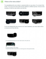
The position of the coil should be as indicated here:
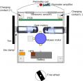
Chassis components

If the robot runs over the perimeter wire (coil is then "outside" of perimeter loop) it will try to get "inside" the loop again by rotating. If getting the coil "inside" the loop by rotating is not possible, the robot will rotate endless.
The more the robot runs over the perimeter, the more difficult it is to get "inside" again by rotation. The robot speed should be reduced as well as moving the coil further outside.
NOTE: It's always a good idea to manually place the robot at the position where you saw the robot detecting the perimeter. The perimeter plot should change from "in" to "out" at that position (http://wiki.ardumower.de/index.php?title=Perimeter_wire#Receiver_diagnostics.2Ftroubleshooting). Then manually rotate the robot (without motor) at that position and verify that "out" changes again to "in". If that is not the case, the position of the coil is not OK or the robot drives too quickly and detects the perimeter too late.
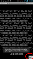
Console output
When the robot starts, it outputs something like this in the serial console:
 START
 Ardumower rXXXX
 press...
   d for menu
   v to change console output (sensor counters, values, perimeter etc.)
t     0 l177 v0 FORW spd   33   33    0 sen    0    0    0 bum    0    0 dro    0    0 son   0 yaw   0 pit   0 rol   0 bat 20.8 chg 21.7  0.0 imu  0 adc  0 Ardumower
t     1 l177 v0 FORW spd   33   33    0 sen    0    0    0 bum    0    0 dro    0    0 son   0 yaw   0 pit   0 rol   0 bat 20.8 chg 21.7  0.0 imu  0 adc  0 Ardumower
t     3 l177 v0 FORW spd   33   33    0 sen    0    0    0 bum    0    0 dro    0    0 son   0 yaw   0 pit   0 rol   0 bat 20.8 chg 21.7  0.0 imu  0 adc  0 Ardumower
Once a sensor triggers, its counter increases.
Example (mower motor current overflow triggered):
t     4 l177 v0 FORW spd   33   33    0 sen    0    0    0 bum    0    0 dro    0    0 son   0 yaw   0 pit   0 rol   0 bat 20.8 chg 21.7  0.0 imu  0 adc  0 Ardumower
t     5 l177 v0 REV  spd  -26  -26    0 sen    0    0    1 bum    0    0 dro    0    0 son   0 yaw   0 pit   0 rol   0 bat 20.8 chg 21.7  0.0 imu  0 adc  1 Ardumower
Here is a description of each column:
t - time of current machine state (ms) l - loop () - cycles per second v - Verbose mode selected sensor (0 = counts / 1 = sensor values / 2 = sensor values) - Current machine status (FORW, REV, ROLL etc.) - After-home-drive? (1/0) spd - control / speed motor: left (PWM), right (PWM), mower (speed) sen - motor current overflow counter: left, right, mower bum - bumper counter: left, right son - ultrasonic distance-below: counter pit, roll - inclination (calculated with Accel sensor) yaw - compass course bat - battery voltage chg - charger voltage sensor
--- commands ---
'd': menu for testing, adjust IMU, Bluetooth
'v': monitorMode (show Value not Counter
'h': drive home
'p': track perimeter
'l': simulate left bumper
'r': simulate right bumper
's': simulate lawn sensor
'm': toggle mower motor
'c': simulate charging
'+': rotate 90 degrees
'-': rotate 90 degrees
'3': activate model RC
'0': OFF
'1': Automode motorMowEnable
Ardumower states
Sensor logging
For PC data analysis, algorithm modelling and optimization, you can collect robot sensor data using pfodApp like this:
- Using your Android pfodApp, connect to your robot and choose 'Log sensors'. The logged sensor data will be displayed. Click 'Back' to stop logging (NOTE: for ArduRemote, press Android menu button before and choose 'Enable logging' to enable file logging).
- Connect your Android phone to the PC, if being asked on the phone choose 'Enable as USB device', so you phone shows as a new Windows drive on your PC.
- On your PC, launch Windows Explorer and choose the new Android drive, browse to the 'pfodAppRawData' folder (for ArduRemote: 'ArduRemote' folder), and copy the data file to your PC (you can identify files by their Bluetooth name and date).
1. Start pfodApp
2. Choose 'Log sensors'
3. Choose phone back button or 'Exit'
4. Connect to your PC via USB, choose 'Enable as USB device'
5. Using Windows explorer, browse to folder 'pfodAppRawData' on external Android drive to access sensor log file
How to report a new bug/new feature/new code
Click on 'this link' and create a new issue - Please let us know:
   Your platform version (Arduino Mega 2560, Arduino Due)
   Your Arduino IDE version (latest code requires 1.6.3)
   Your exact operating system (Windows 8, Linux etc.)
   Your Ardumower code version (for a list of releases see https://github.com/Ardumower/ardumower/releases)
   Any other information that may be useful...
IMU calibration steps
Acceleration sensor
This calibration can be performed outside of the robot. Place each of the 6 module sides exactly upright, do not move and choose 'next side calibration':
- Via serial console "IMU acc calibration next side" OR
- Via pfodApp "Settings->IMU->acc calibration next side"
Do not move the module during the measurement of each side! During measurement you will hear a short beep tone.
Repeat this step for all 6 sides. After all 6 sides are calibrated, you will hear a short melody.

Compass sensor
This calibration can only be performed inside of the robot (IMU in its final position). Start the compass calibration:
- Via serial console "IMU com calibration start/stop" OR
- Via pfodApp "Settings->IMU->com calibration start/stop"
Hold each of the 6 module sides to North direction and tilt the module until minimum and maximum of the axis does not change anymore (until no tone is outputted anymore):

Calibration quality test
For a quality test, you can plot the calibration results (Yaw, Pitch, Roll) via pfodApp. Place the robot on a flat ground and let it rotate (pfodApp: click on "Commands->Auto rotate" until robot rotates). Alternatively, you can let the robot drive a circle (pfodApp: click "Manual->Right" until it drives the desired radius). Finally, choose 'Plot->IMU' to see the calibration result.
For the yaw plot, the curve should be a straight line when the robot is rotating with a constant speed.
