Azurit Firmware (English): Unterschied zwischen den Versionen
(→Uploading the Arduino code to your Arduino) |
(→Uploading the Arduino code to your Arduino) |
||
| Zeile 14: | Zeile 14: | ||
* In file 'mower.h', choose the correct <b>motor drivers</b> (DRIVER_MC33926 or DRIVER_L298N) - in most cases, DRIVER_MC33926 the correct one | * In file 'mower.h', choose the correct <b>motor drivers</b> (DRIVER_MC33926 or DRIVER_L298N) - in most cases, DRIVER_MC33926 the correct one | ||
* <b>Upload</b> the code to your Arduino board | * <b>Upload</b> the code to your Arduino board | ||
| − | + | ||
| + | =Serial console= | ||
| + | After successfully uploading, open the Arduino IDE <b>serial console</b> and choose baud rate 19200. You should see something like this: | ||
ADCMan: found calib data | ADCMan: found calib data | ||
---ADC calib--- | ---ADC calib--- | ||
Version vom 5. Juli 2017, 15:38 Uhr
This page describes how to flash the Arduino for your robot mower, configure the robot mower and look for errors.
Inhaltsverzeichnis
- 1 Uploading the Arduino code to your Arduino
- 2 Serial console
- 3 Settings
- 4 First-time usage
- 5 Starting the mower
- 6 Console output
- 7 Motor controller (PID)
- 8 Bluetooth module
- 9 Diagnostics/troubleshooting
- 9.1 Hardware measurements
- 9.2 Error codes
- 9.3 I2C errors
- 9.4 Disable all pins not connected
- 9.5 Motors working correctly
- 9.6 Any unexpected sensor triggering
- 9.7 Some sensor not triggering?
- 9.8 Bluetooth not connecting?
- 9.9 Robot not stopping to rotate when reaching perimeter (home mode)
- 9.10 More troubleshooting
- 10 Sensor logging
- 11 How to report a new bug/new feature/new code
- 12 Charging
- 13 IMU
- 14 IMU calibration steps
- 15 Perimeter receiver
- 16 GPS
- 17 Timer
- 18 Drop sensor
- 19 Finite state machine
Uploading the Arduino code to your Arduino
NOTE: If you have never worked with Arduino before, read our 'Arduino first steps' introduction.
- Download an Ardumower Release at Github
- Download the Arduino IDE that we will use to upload the code to your Arduino
- Start Arduino IDE, and choose the right Arduino board (either Mega 2560 or Due)
- In file 'mower.h', choose the correct PCB (PCB_1_2 or PCB_1_3) - Example for choosing PCB 1.3 (a line started with // will be ignored):
// #define PCB_1_2
#define PCB_1_3
- In file 'mower.h', choose the correct robot type (ROBOT_ARDUMOWER or ROBOT_MINI)
- In file 'mower.h', choose the correct motor drivers (DRIVER_MC33926 or DRIVER_L298N) - in most cases, DRIVER_MC33926 the correct one
- Upload the code to your Arduino board
Serial console
After successfully uploading, open the Arduino IDE serial console and choose baud rate 19200. You should see something like this:
ADCMan: found calib data
---ADC calib---
ADC sampleRate=38462
AD0	min=9999	max=-9999	diff=-19998	ofs=334
AD1	min=9999	max=-9999	diff=-19998	ofs=417
...
SETUP
matchSignal size=24
subSample=4
capture size=192
1	0	-1	0	1	-1	1	-1	0	1	-1	1	0	-1	0	1  -1	0	1	-1	0	1	0	-1
IMU error: no calib data
--------
accOfs=0.00,0.00,0.00
accScale=2.00,2.00,2.00
comOfs=0.00,0.00,0.00
comScale=2.00,2.00,2.00
--------
initL3G4200D
gyro read error
gyro read error
gyro read error
loadSaveErrorCounters: read
loadSaveErrorCounters addrstop=423
loadUserSettings
EEPROM USERDATA: NO EEPROM USER DATA
PLEASE CHECK AND SAVE YOUR SETTINGS
loadSaveRobotStats: read
loadSaveRobotStats addrstop=822
START
Ardumower 1.0a8-Azurit-dev  PCB 1.3  Arduino Mega  IOREF=5.00
Robot: Mini
press...
 d for menu
 v to change console output (sensor counters, values, perimeter etc.)
sen_counters
t     1 L  0 m0 OFF  rpm    0    0 set    0    0 sen    0    0    0 bum    0    0 dro    0    0 son   0 yaw   0 pit   0 rol   0 bat 677.0 chg 677.0  0.0 imu  0 adc  0 Mini
Settings
The robot uses settings that you can adjust for your own robot and environment (via pfodApp or directly in the code). The default settings (factory settings) are stored in the config file 'mower.cpp'. In this file you can find a description of all settings.
The settings can be adjusted via Android phone (pfodApp).
Visualization of settings
Motor speed settings


Important: If you uploaded a new version into your robot, reset all settings via pfodApp once (Settings->Factory reset). This will delete all existing settings. Old settings can produce malfunction if the internal settings format has changed.
First-time usage
1. At first, deactivate all sensors - In 'mower.cpp' set the robot settings like this:
bumperUse = 0;
dropUse = 0;
rainUse = 0;
sonarUse = 0;
perimeterUse = 0;
lawnSensorUse = 0;
imuUse = 0;
batMonitor = 0;
odometryUse = 0;
gpsUse = 0;
buttonUse = 1;
timerUse = 0;
2. The software offers a serial console mode. Open the serial console in the Arduino IDE (CTRL+SHIFT+M) and set the baudrate to 19200. The motor and sensor values should appear constantly. First let's delete any existing error. Send the letter 'd' to the Arduino.
Console:
press...
d for menu
e=delete all errors
3. Run the ADC calibration, so that the ADC signals are symmetric around zero.
pres...
8=ADC calib (perimeter sender, charger must be off)
4. Save user settings
press...
9=saver user settings
5. Test motors:
press...
1=test motors

Security note: For security reasons, always remove mower blades in your first tests!
You should verify that the wheel motors are controlled correctly and in the right direction. Increase 'motorAccel' in 'mega.cpp' if the motors are not accelerating quickly enough.
Starting the mower
To start the mower, you need to add a button and a buzzer:
pinButton —o Button o— GND (button for ON/OFF)
pinBuzzer —o Buzzer o— GND (Piezo buzzer)
Now, press the button as long as you hear the beeps:
Mode (press button for x beeps):
1 beeps : Normal mowing (using blade modulation if available)
2 beeps : Normal mowing (without blade modulation)
3 beeps : Drive by model remote control (RC)
4 beeps : Drive without mowing
5 beeps : Find perimeter and track it
Console output
When the robot starts, it outputs something like this in the serial console:
 START
 Ardumower rXXXX
 press...
   d for menu
   v to change console output (sensor counters, values, perimeter etc.)
t     0 l177 v0 FORW spd   33   33    0 sen    0    0    0 bum    0    0 dro    0    0 son   0 yaw   0 pit   0 rol   0 bat 20.8 chg 21.7  0.0 imu  0 adc  0 Ardumower
t     1 l177 v0 FORW spd   33   33    0 sen    0    0    0 bum    0    0 dro    0    0 son   0 yaw   0 pit   0 rol   0 bat 20.8 chg 21.7  0.0 imu  0 adc  0 Ardumower
t     3 l177 v0 FORW spd   33   33    0 sen    0    0    0 bum    0    0 dro    0    0 son   0 yaw   0 pit   0 rol   0 bat 20.8 chg 21.7  0.0 imu  0 adc  0 Ardumower
Once a sensor triggers, its counter increases.
Example (mower motor current overflow triggered):
t     4 l177 v0 FORW spd   33   33    0 sen    0    0    0 bum    0    0 dro    0    0 son   0 yaw   0 pit   0 rol   0 bat 20.8 chg 21.7  0.0 imu  0 adc  0 Ardumower
t     5 l177 v0 REV  spd  -26  -26    0 sen    0    0    1 bum    0    0 dro    0    0 son   0 yaw   0 pit   0 rol   0 bat 20.8 chg 21.7  0.0 imu  0 adc  1 Ardumower
Here is a description of each column:
t - time of current machine state (ms) l - loop () - cycles per second v - Verbose mode selected sensor (0 = counts / 1 = sensor values / 2 = sensor values) - Current machine status (FORW, REV, ROLL etc.) - After-home-drive? (1/0) spd - control / speed motor: left (PWM), right (PWM), mower (speed) sen - motor current overflow counter: left, right, mower bum - bumper counter: left, right son - ultrasonic distance-below: counter pit, roll - inclination (calculated with Accel sensor) yaw - compass course bat - battery voltage chg - charger voltage sensor
--- commands ---
'd': menu for testing, adjust IMU, Bluetooth
'v': monitorMode (show Value not Counter
'h': drive home
'p': track perimeter
'l': simulate left bumper
'r': simulate right bumper
's': simulate lawn sensor
'm': toggle mower motor
'c': simulate charging
'+': rotate 90 degrees
'-': rotate 90 degrees
'3': activate model RC
'0': OFF
'1': Automode motorMowEnable
Ardumower states

Motor controller (PID)
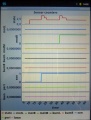
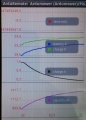
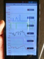
The speed of the motors is controlled by a software PID controller. You can monitor the quality of the motor speed control via pfodApp (Plot->Motor control):
Motor speed settings

Bluetooth module
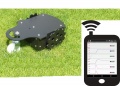
The Ardumower can be monitored and controlled wirelessly:
- via phone/tablet (Android App)
- via USB Bluetooth dongle (PC serial console)
On the phone, you'll need the App 'ArduRemote'. Alternatively, you can use the App 'pfodApp'.
The phone menu includes:
- Status information (battery voltage, charging current etc.)
- Settings (Timer etc.)
- Calibration (Motor, IMU etc.)
- Remote control (Start/Stop, Switching on/off mower motor, blade modulation etc.)

Live configuration, monitoring and debugging
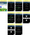
Android app menus

Android app (pfodApp)

Android app (ArduRemote)
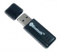
PC communication via Bluetooth USB dongle


Bluetooth module
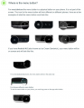
On the robot, you'll need a Bluetooth HC-05 module supporting Bluetooth Serial Port Profile (SPP). SPP uses Bluetooth Service Discovery Protocol (SDP) and the RFCOMM protocol.
Bluetooth HC-05
For Programming the Module, you must connect the Key Pin from the BT Module to the 3.3 V from the PCB and disconnect after programming.
Bluetooth module configuration steps
- Configuration mode: The Bluetooth module must be in configuration mode for the next step:
- for HC05: Connect KEY pin to 3.3V after powering on the module
- for HC06/linvor: Do NOT pair/connect (LED must be blinking)
- for FBT06/MBTV4: First you have to solder the PIO11 pin to VCC (PIN 12) which is 3.3 Volts using a thin wire.
- Baud rate: Blueooth module and Arduino Mega must use the same baud rate (19200) - The baud rate of the BT module can be changed via Ardumower serial console. Connect Ardumower Mega board to your PC (USB), enter the serial console in the Arduino IDE (CTRL+M), and choose baud rate 19200, then choose 'd' to enter the Ardumower menu, '3' for communications menu, and '3' to configure the module to the correct baud rate.
- Restart: After your BT module is configured successfully, remove KEY pin connection again (HC05), and restart module.
- Pairing: The BT module must be 'paired' with your Android device once (via Android device settings). On the Android device, choose symbol "Settings" (via Android menu). Now choose "Wirless and Networks->Bluetooth Settings" and "Find device". Finally, choose "pair with this device" and enter your pin (very often "1234"). The Bluetooth module should now appear as "paired".
- pfodApp: Now you can start pfodApp/ArduRemote to connect to the Ardumower.
PC/Mac remote control application
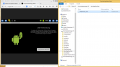
In addition to the Android App, we have developed a remote control application for PC/Mac/Linux (developed in Processing/Java). The Mac standalone version has to be created within Processing, the Windows version is already available as standalone version:
- Download Windows 64 bit executable and extract it:
https://drive.google.com/uc?export=download&confirm=EYiA&id=0B90Bcwohn5_HRFFMUUFYWF9OdW8
- Download and install Java runtime (version 8 or higher): https://java.com/de/download/
- Plug-in an USB bluetooth dongle on your PC
- In Windows, pair the USB bluetooth dongle with the Ardumower bluetooth module - two new serial ports will be created on your PC (the first for incoming bluetooth connections, the 2nd one for outgoing bluetoth connections)
- Run 'processing_remote.exe', all available serial ports will be shown - select the serial port for outgoing connections
The code for Processing can be found here: https://github.com/Ardumower/ardumower/tree/master/code/Test_und_Entwicklung/processing_remote
Processing can be downloaded here: https://processing.org/
Communication protocol
You can log the communication to a file (folder 'pfodAppRawData' or 'ArduRemote') on your Android device. For the ArduRemote, press the 'Android menu button' on your device and choose 'Enable logging'.
Android menu button

Sensor logging
For PC data analysis, algorithm modelling and optimization, you can collect robot sensor data using pfodApp like this:
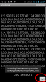
- Using your Android pfodApp, connect to your robot and choose 'Log sensors'. The logged sensor data will be displayed. Click 'Back' to stop logging (NOTE: for ArduRemote, press Android menu button before and choose 'Enable logging' to enable file logging).
- Connect your Android phone to the PC, if being asked on the phone choose 'Enable as USB device', so you phone shows as a new Windows drive on your PC.
- On your PC, launch Windows Explorer and choose the new Android drive, browse to the 'pfodAppRawData' folder (for ArduRemote: 'ArduRemote' folder), and copy the data file to your PC (you can identify files by their Bluetooth name and date).

1. Start pfodApp
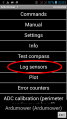
2. Choose 'Log sensors'
3. Choose phone back button or 'Exit'

4. Connect to your PC via USB, choose 'Enable as USB device'
5. Using Windows explorer, browse to folder 'pfodAppRawData' on external Android drive to access sensor log file


Videos
Diagnostics/troubleshooting
Each time a sensor triggers, its corresponding sensor counter increases. The sensor trigger counters as well as the current sensor values can be viewed on the serial console. The following values are shown for the trigger counters in the serial console:
- Time of state machine's state (ms)
- loop()-counts per second
- choosen Verbose-Mode (0=counter readings/1=current values/2=current values)
- current state machine state (FORW, REV, ROLL etc.)
- drive home? (1/0)
- "spd" - Control/speed motors: left (PWM), right (PWM), mower (RPM)
- "sen" - Current limit exceeded counter motors: left, right, mower
- "bum" - bumper counter: left, right
- "son" - Ultrasonic-distance threshold exceeded (counter)
- "pit/roll" - Tilt (computed by acceleration sensor)
- "com" - compass course
- "per" - Perimeter loop detected: counter
- "bat" - Battery voltage
- "chg" - Charging current
Using the key 'v', you can toggle between sensor trigger counters and current sensor values.
![]() Additionally, you can use pfodApp (Android) to plot the sensors (trigger counters and current values) over time. This allows you to wirelessly monitor your robot mower for error diagnostics. It is highly recommended.
Additionally, you can use pfodApp (Android) to plot the sensors (trigger counters and current values) over time. This allows you to wirelessly monitor your robot mower for error diagnostics. It is highly recommended.
Sensor trigger counters
Sensor measurement values
Ardumower states


Hardware measurements
For detecting failures in the assembly or electronic parts, it is highly recommended to use an oscillscope (e.g. pocket oscillscope DSO201) for your measurements. An Oscilloscope allows you to detect short-time failures in power signals, perimeter sender and receiver signals, odometry signals and more.

Tutorial for pocket oscilloscopes: http://www.ardumower.de/index.php/de/forum/anleitungen-hilfe/142-bedienung-oszilloskop-dso201
Error codes
If your robot beeps periodically, it is in ERROR state. Either run the serial console or 'pfodApp->Error Counters' to find out the detailed error. The possible solutions for each error are given below. For details about your robot settings, see Settings.
 ERR_CPU_SPEED           CPU speed error
                         * Check I2C cables (e.g. reduce wire length)
 ERR_MOTOR_LEFT          Left gear motor error
                         * Check gear motor driver module and left gear motor (supply voltage, signal lines)
                         * MC33926: ensure SLEW jumper is not set
                         * Tracking: reduce Motor-Max-PWM and Tracking-P to reduce EMF
 ERR_MOTOR_RIGHT         Right gear motor error
                         * Check gear motor driver module and right gear motor (supply voltage, signal lines)
                         * MC33926: ensure SLEW jumper is not set
                         * Tracking: reduce Motor-Max-PWM and Tracking-P to reduce EMF
 ERR_MOTOR_MOW           Mower motor error
                         * Check mower motor driver module and mower motor (supply voltage, signal lines)
                         * MC33926: ensure SLEW jumper is not set
                         * Reduce Motor-Max-Power, so over-current is detected earlier
 ERR_MOW_SENSE           Mower motor over-current
                         * Check mower motor driver module and mower motor
                         * Increase Motor-Max-Power, so over-current is detected later
 ERR_IMU_COMM            IMU communication error
                         * Check IMU module connections
 ERR_IMU_CALIB           IMU calibration error
                         * Start IMU calibration (either via Console or pfodApp->Settings->IMU)
 ERR_IMU_TILT            IMU tilt error
                         * Check IMU module and robot orientation
 ERR_RTC_COMM            RTC communication error
                         * Check RTC module connections, RTC battery etc.
 ERR_RTC_DATA            RTC corrupt data error
                         * Set and save RTC date and time
 ERR_PERIMETER_TIMEOUT   Perimeter signal timeout
                         * Check perimeter sender, wire etc.
                         * Check coil polarity
                         * Reduce Perimeter-smag, so timeout is higher
                         * Increase Perimeter-timeout-seconds, so timeout is higher
                         * Check your signal-to-noise ratio is higher than 1.0
 ERR_TRACKING            Perimeter tracking error
                         * Check perimeter sender, wire etc.
                         * Increase Perimeter-tracking-timeout, so timeout is higher
 ERR_ODOMETRY_LEFT       Left motor odometry error
                         * Check left odometry cable
                         * Check left motor direction
 ERR_ODOMETRY_RIGHT      Right motor odometry error
                         * Check right odometry cable
                         * Check right motor direction
 ERR_BATTERY             Battery error
                         * Check battery connections
 ERR_CHARGER             Charger error
                         * Check charger connections
 ERR_GPS_COMM            GPS communication error
                         * Check GPS cables
 ERR_GPS_DATA            GPS data error
                         * Check GPS antenna and cable
 ERR_ADC_CALIB           ADC calibration error
                         * Start ADC calibration (either via Console or pfodApp->ADC calibration)
 ERR_EEPROM_DATA         EEPROM data error
                         * Save user settings (either via Console or pfodApp->Settings-Save)
After fixing the error, you can delete errors:
Console:
press...
d for menu
e=delete all errors
I2C errors
Ensure the I2C bus is working correctly. A console stucked at line 'initL3G4200D' indicates I2C is not working correctly. If there's a communication problem or another serious problem, the error counter increases. The error counter can be monitored via pfodApp. Additionally, the robot mower will beep when started.
Several components (Arduino Nano, RTC, IMU, etc.) are communicating via the I2C bus (SDA/SCL wires). These wires should be very short (maybe even twisted) and they should be far away from DC converter and motor drivers. If there's a communication problem, the error counter will increase and robot will beep when started. The error counter can be monitored via pfodApp.
Disable all pins not connected
Ensure that you have disabled all features and pins in the robot configuration that are not connected (not used).
Example: If you do not have connected odometry pins, disable them in the robot config (robot.cpp):
odometryUse = 0; // use odometry?
Motors working correctly
Run the serial console (Arduino IDE: CTRL+SHIFT+M, 19200 Baud) and press 'd' and ENTER for menu. Then press '1' and ENTER to run the motor test.
Any unexpected sensor triggering
If your robot does something unexpected, it might be a sensor that is incorrectly triggering. Check this via the serial console:
Run the serial console (Arduino IDE: CTRL+SHIFT+M, 19200 Baud), and start the robot. Each time a sensor triggers, the counter of that sensor will increase. See description of each sensor below. Now when your robot does something unexpected, have a look which of the sensor counters increased to locate the problem.
Some sensor not triggering?
...
Bluetooth not connecting?
- Verify that BT module baudrate is configured properly (using Ardumower Console) - activate programming button on BT module for programming procedure.
- Verify that BT module is 'paired' on your Android phone
- Verify that Arduino Mega is not powered via USB (but DC/DC instead)
Robot not stopping to rotate when reaching perimeter (home mode)
At first, verify that the perimeter tracking itself is working: Manually put the robot on the perimeter wire, and via ArduRemote App, choose 'Commands->Track' and verify the robot is tracking the perimeter. If it does not, adjusting the tracking PID parameters may help.
The position of the coil should be as indicated here:
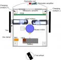
Chassis components

If the robot runs over the perimeter wire (coil is then "outside" of perimeter loop) it will try to get "inside" the loop again by rotating. If getting the coil "inside" the loop by rotating is not possible, the robot will rotate endless.
The more the robot runs over the perimeter, the more difficult it is to get "inside" again by rotation. The robot speed should be reduced as well as moving the coil further outside.
NOTE: It's always a good idea to manually place the robot at the position where you saw the robot detecting the perimeter. The perimeter plot should change from "in" to "out" at that position (http://wiki.ardumower.de/index.php?title=Perimeter_wire#Receiver_diagnostics.2Ftroubleshooting). Then manually rotate the robot (without motor) at that position and verify that "out" changes again to "in". If that is not the case, the position of the coil is not OK or the robot drives too quickly and detects the perimeter too late.
More troubleshooting
- Änderungen der Konfigurationseinstellungen in der Mower.cpp Datei werden nicht übernommen
- Der Ladestrom im ArduMower zeigt nichts oder falsche Werte an
- Der Perimetersender ohne automatische Regelung
- Elektrische Fehlersuche am BT Modul
- Programmieranleitung für das Bluetooth Modul auf der Platine V1.2
Sensor logging
For PC data analysis, algorithm modelling and optimization, you can collect robot sensor data using pfodApp like this:
- Using your Android pfodApp, connect to your robot and choose 'Log sensors'. The logged sensor data will be displayed. Click 'Back' to stop logging (NOTE: for ArduRemote, press Android menu button before and choose 'Enable logging' to enable file logging).
- Connect your Android phone to the PC, if being asked on the phone choose 'Enable as USB device', so you phone shows as a new Windows drive on your PC.
- On your PC, launch Windows Explorer and choose the new Android drive, browse to the 'pfodAppRawData' folder (for ArduRemote: 'ArduRemote' folder), and copy the data file to your PC (you can identify files by their Bluetooth name and date).
1. Start pfodApp
2. Choose 'Log sensors'
3. Choose phone back button or 'Exit'
4. Connect to your PC via USB, choose 'Enable as USB device'
5. Using Windows explorer, browse to folder 'pfodAppRawData' on external Android drive to access sensor log file
How to report a new bug/new feature/new code
Click on 'this link' and create a new issue - Please let us know:
   Your platform version (Arduino Mega 2560, Arduino Due)
   Your Arduino IDE version (latest code requires 1.6.3)
   Your exact operating system (Windows 8, Linux etc.)
   Your Ardumower code version (for a list of releases see https://github.com/Ardumower/ardumower/releases)
   Any other information that may be useful...
Charging
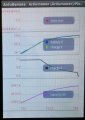
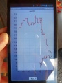
In the robot itself, the battery voltage is monitored (see diagram below). So it can be determined when the robot must go to the charging station. The robot and the voltage and the current during charging is controlled. So it can be determined whether the robot has reached the charger and when the battery is fully charged again.
Via pfodApp (Android) you can monitor the charging process.
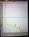
Charging plot
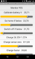
Battery settings
Battery fully charged
Charging with timeout


IMU
An IMU (Intertia Measurement Unit) is a key component of an inertia navigation system. We use it to:
- detect if the robot is in tilt orientation
- keep the robot on track for the 'lane-by-lane' mowing pattern

Acceleration sensor
An acceleration sensor measures earth gravity force (m*s^2) in all 3 robot axes (x/y/z) allowing you to calculate the orientation towards earth center of the robot (Roll, Pitch). However, it cannot detect movement around Yaw - this requires a gyro.

Gyro
A gyro measures rotational speed (degree/second) in all 3 robot axes (Roll, Pitch, Yaw). This allows us to correct the robot if it is driving 'off-course' due to wet conditions or slope. When integrating (adding) gyro values over time, the actual course (yaw) can be calculated. However, because each sensor reading has a small error, the course will 'drift' over time. This needs to be corrected via an absolute heading sensor (compass).
Typical gyro measurement errors:
                noise dps/sqrt(Hz)
L3G4200D        0.03
ITG3200         0.03
L3GD20          0.03
BMG160/BNO055   0.014
MPU9250         0.01
L3GD20H         0.011
LSM9DS0         0.00875
BMI160          0.007
MAX21003        0.007
L2G2IS/L2G3IS   0.006
MPU9150/MPU6050 0.005
ADXRS290        0.004
CRM100/200      0.003
GYPRO2300       0.00277
Compass
If a robot drives on a wet lawn, you'll notice quickly that it will not drive straight forward, but instead tends to drive into the direction of the slope. Reading a compass heading can solve this problem and the robot will drive straight forward again .
However, a compass has two problems:
- If tilting the robot, the compass measurements (x,y,z) relate to the tilted robot. So, you need to correct them using knowing the tilt angles. This requires the use of the accerlation sensor (x,y).
- The compass measurements are influenced by motors. So you may need to switch of the motor to get an accurate measurement.
Typical compass measurement errors:
                        sensitivity (uT)       typical heading error (degree)
AK8975 (MPU9150)        0.3                    5
BNO055                  0.3                    2.5
CMPS11 (9S0 2413 530BS)                        2.0
HMC5883L (GY-80)        0.2                    1.5
AK8963 (MPU9250)        0.15                   not tested
LIS3MDL                 0.14                   not tested
LSM303DLM
MAG3110/FXOS8700CQ      0.1                    not tested
IMU sensor fusion
To eliminate the issues of all sensor, they are merged to compute the course (degree) and pitch/roll angles.
We use a complementary filter to fusion all sensor values.

IMU module
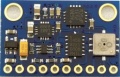
GY-80 module
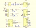
GY-80 schematics


GY-80
- Acceleration sensor: ADXL345B
- Compass sensor: HMC5883L
- Gyro: L3G4200D
- Pressure sensor: BMP085 (not used here)
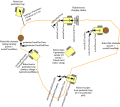
Assembly
This photo shows how the IMU module is placed in the driving position (the red arrow shows the driving position). Ensure a minimum distance of 30cm from all motors. This minimum distance seems to be needed to ensure the compass is not disturbed by dynamically disturbing sources (like motors).

IMU calibration steps
Acceleration sensor
This calibration can be performed outside of the robot. Place each of the 6 module sides exactly upright, do not move and choose 'next side calibration':
- Via serial console "IMU acc calibration next side" OR
- Via pfodApp "Settings->IMU->acc calibration next side"
Do not move the module during the measurement of each side! During measurement you will hear a short beep tone.
Repeat this step for all 6 sides. After all 6 sides are calibrated, you will hear a short melody.

Compass sensor
This calibration can only be performed inside of the robot (IMU in its final position). Start the compass calibration:
- Via serial console "IMU com calibration start/stop" OR
- Via pfodApp "Settings->IMU->com calibration start/stop"
Hold each of the 6 module sides to North direction and tilt the module until minimum and maximum of the axis does not change anymore (until no tone is outputted anymore):

Calibration quality test
For a quality test, you can plot the calibration results (Yaw, Pitch, Roll) via pfodApp. Place the robot on a flat ground and let it rotate (pfodApp: click on "Commands->Auto rotate" until robot rotates). Alternatively, you can let the robot drive a circle (pfodApp: click "Manual->Right" until it drives the desired radius). Finally, choose 'Plot->IMU' to see the calibration result.
For the yaw plot, the curve should be a straight line when the robot is rotating with a constant speed.

Perimeter receiver
Perimeter settings
At first, activate the perimeter in the Ardumower software (pfodApp->Options->Perimeter Use: YES). It is recommended to keep the default perimeter settings.
The perimeter settings are:
- Timed-out if below smag (timedOutIfBelowSmag) - default setting: 300 | If smag below this value, sender is considered as off (perimeter timeout appears)
- Timeout (s) if not inside (timeOutSecIfNotInside) - default setting: 8
- Trigger timeout (perimeterTriggerTimeout) - default setting: 0 | Perimeter outside trigger timeout when escaping from inside (ms)
- Perimeter out roll time max (perimeterOutRollTimeMax) - default setting: 2000 | Max (random generator) roll time after perimeter out (ms)
- Perimeter out roll time min (perimeterOutRollTimeMin) - default setting: 750 | Min (random generator) roll time after perimeter out (ms)
- Perimeter out reverse time (perimeterOutRevTime) - default setting: 2200 | Time to drive reverse after perimeter out (ms)
- Perimeter tracking roll time (perimeterTrackRollTime) - default setting: 1500 | Hit obstacle while tracking: roll time
- Perimeter tracking reverse time (perimeterTrackRevTime) - default setting: 2200 | Hit obstacle while tracking: reverse time
- Transition timeout (trackingPerimeterTransitionTimeOut) - default setting: 2000 | Max. time required for a in/out transition during tracking, robot will start rotating after this timeout
- Track error timeout (trackingErrorTimeOut) - default setting: 10000 | Max. time required for a in/out transition during tracking, robot will go into error after this time
- Track_P (perimeterPID.Kp) - default setting:51 | Perimeter PID "P" setting
- Track_I (perimeterPID.Ki) - default setting:12.5 | Perimeter PID "I" setting
- Track_D (perimeterPID.Kd) - default setting:0.8 | Perimeter PID "D" setting
- Use differential signal (useDifferentialPerimeterSignal) - default setting: YES | Use differential signal (see signal section)
- Swap coil polarity (swapCoilPolarity) - default setting:NO
- Block inner wheel (trackingBlockInnerWheelWhilePerimeterStruggling) - default setting: YES | robot is wheel-spinning while tracking => roll to get ground again
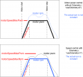
Receiver ADC calibration
![]() The ADC calibration ensures that the zero point (silence) is detected correctly, and so later the received signal is symmetric around zero.
The ADC calibration ensures that the zero point (silence) is detected correctly, and so later the received signal is symmetric around zero.
- The perimeter sender and robot motors must be switched off during calibration!
- If you cannot avoid that another sender is disturbing during calibration, remove the coil during calibration (connect LM386 input line to GND)
- Run the ADC calibration once ("pfodApp->ADC Calibration")
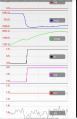
When calibrated correctly, the signal in the pfodApp plot ('sig') should be around zero (0) when the perimeter sender is switched off. When the perimeter sender is switched on, the plotted signal ('sig') should have the same maximum amplitude for both positive and negative axis (is 'symmetric around zero').
symmetric signal when sender is on (after ADC calibration)
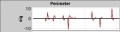
zero signal when sender is off (after ADC calibration)

Receiver diagnostics/troubleshooting
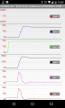
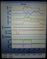
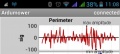
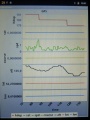
The receiver signal, filter result and signal quality can be monitored via Android phone (pfodApp->Plot->Perimeter):
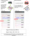
Signal-to-noise ratio (SNR)
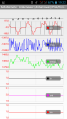
signal, filter result, LP filter result, inside/outside, counter, on/off, quality
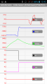
Moving from inside to outside


Plot signal description:
sig:  coil signal (raw pulse sequence after ADC) - it's a short snapshot (32 samples), and it's taken every 20 seconds
      (so you need to wait 20 seconds for the next snapshot)
mag:  filter result: inside (negative) or outside (positive), magnitude: distance to perimeter wire/magnetic signal strength (RSSI)
      - this is used for perimeter tracking
smag: filter result, low-pass filtered, without sign (smooth mag) - this is used for 'sender-off' detection
      The threshold can bet set via pfodApp (Settings->Perimeter->Timed-out if below smag)
in:   binary result, low-pass filtered: inside (1) oder outside (0) - this is used for perimeter boundary detection
      If the robot is not inisde for a certain time, it will go into error. The threshold can bet set via pfodApp
      (Settings->Perimeter->Timeout (s) if not inside)
cnt:  number of "inside-outside" transitions (counter)
on:   perimeter sender active, robot is inside and smag is high enough (1) or inactive/outside/smag too low (0)
qty:  signal quality (how distinguisable inside and outside were in filter result
      computes ratio:  match score with template signal / match score with inverse template signal
      1.0 means poor quality, you should get 1.5 or higher)
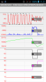
The 'mag' plot should be clear (without spikes): Inside the perimeter loop, the signal should be a clear negative curve, outside it should be a clear positive curve. If your 'mag' curve is not clear (and has spikes), try to troubleshoot/optimize:
- Verify, your coil is connected correctly at 'pinPerimeterLeft' (you still may get a poor signal when connected at a wrong Arduino pin!)
- Decrease the threshold for a smag timeout via 'pfodApp->Options->Perimeter->Timed-out if below smag'
- Reverse coil if the in/out is inverted or reverse the perimeter wire
- Minimize cable length between coil and LM386-pre-amplifier (directly mount coil onto pre-amplifier)
- Increase distance between coil and mower motor/DC converter (move away coil 30cm or more from any motors or DC converters)
- Add some magnetic shield (e.g. your battery) between coil and motors/DC converter
Tracking of perimeter
The tracking of the perimeter wire is performed using a (software) digital PID controller. The controller's parameters (P,I,D) can be configured via the phone (pfodApp).

You can find more information about PID controllers here: Forum.
GPS
With the help of a GPS receiver (e.g. GY-NEO6MV2, ublox 6m), the long-term position can be calculated. Therefore, the GPS position values will be averaged.
Currently, GPS is used
- to receive current date and time
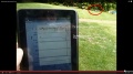
Visualization of GPS data
GPS data (course, speed, position etc.) can be plotted by pfodApp. One neat thing I discovered is that you can get precise heading and speed even when moving short distances (< 2m). This works because the GPS receiver is evaluating the signal phase due to the doppler effect.
hdop    measurement error indication (the more satellites are from different directions, the lower the error)
sat     number of satellites in view
spd     ground speed m/s
course  ground course degree
alt     altitude meter
lat     latitude
lon     longitude
GPS plot
GPS plot (heading/speed via doppler effect)
GPS 2d map (tracked perimeter)


GPS error
Typical GPS error is 2-5 meters (at a sample rate of 1 Hz). As this is not sufficient as a replacement for a perimeter wire, GPS can only be seen as an extension or for global navigation (navigation from one lawn to another lawn).
Timer
On the robot, several timers can be programmed (via Android pfodApp). For each timer, you can define a time interval ('time windows') for the desired days. As long as the actual time is within any time window, the robot can freely mow, charge, mow, charge etc.
Example:
Timer 1: 08:00 - 13:00 Monday, Thuesday, Wednesday
Timer 2: 14:00 - 16:00 every day
Timer 3: off
Timer 4: off
Drop sensor
Einstellung im Sketsch:
Die Absturzsensoren sind ab der Softwarefunktion 242 integriert.
(Eine Integration in die Handy App bzw. das persönliche Speicher der Einstellungen ist zur Zeit noch nicht Intrigiert.)
Der Anschluss des linken und rechten Absturzsensor sind an den Pin 45 und 23 vorgesehen.
Um die Funktion zu aktivieren sind folgende Einstellungen in der Mower.ccp vorzunehmen.
//  ------ drop -----------------------------------
 dropUse          = 1;     // has drops?  -Dropsensor - Absturzsensor vorhanden 0-nein  1-Ja
 dropcontact      = 1;     //contact Kontaktausführung 0-Öffner 1-Schließer
Verdrahtung:
Die IR Sensoren sollten möglichst weit vorne vor den Rädern angebracht werden. Um evl Reichweiten Schwankungen zu vermeiden sollten sie vor fremd Licht geschützt werden. Die IR Sensoren sollten so eingestellt werden das diese im normalen Betrieb leuchten, und wenn man den Mover hochhebt ausgehen. Am besten gleich auf der Grasoberfläche testen oder dort zumindest gegebenenfalls nachjustieren. In der Seriellen Ausgabe kann man den richtigen Anschluss kontrollieren. Sollte der Mover im Normalbetrieb den Kontakt zur Oberfläche haben sollte der Dropsensor nicht ausgelöst sein bzw der Counter des Dropsensors sollte nicht hochgezählt werden. Fall das so nicht sein sollte, ist die Einstellung in der Mower.ccp Datei zu kontrollieren bzw. zu ändern.
Dropcontact = 1; ändern in 0
(Kann je nach verwendeten Sensoren anders sein) Danach den Mower anheben so das dieser den Kontakt zur Oberfläche verliert. Darauf hin sollte in der seriellen Konsole sichtbar sein das der Dropsensor ausgelöst hat bzw. der Counter hoch zählt. Darauf hin kann das ganze im automatischen Betrieb getestet werden.
Gegebenenfalls muss noch die Acceleration angepasst werden. Diese ist auch in der Mower.ccp Datei zu finden. Das ist die Beschleunigungszeit bzw. die Abbremszeit der Antriebsmotoren. Dieser Wert muss angepasst (erhöht) werden damit der Mower schnell genug an der Gefahrenstelle anhalten kann.
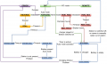
Finite state machine
This section describes some internals of the Ardumower software architecture. Kurz zum Ablauf der Software: In der Hauptschleife (loop) werden periodisch:
- Die Sensoren eingelesen (readSensors)
- Der Zustandsautomat durchlaufen und abhängig vom aktuellen Zustand die Sensorwerte überprüft (CheckXXXXX) und von den Sensorwerten in neue Zustände gewechselt (setNextState) - beim Wechsel werden ggf. neue Soll-Werte für die Motoren gesetzt (Beispiel: motorLeftSpeedRpmSet).
- Die Motoren mit den Soll-Werten angesteuert (motorControl)
Die möglichen Zustände und Ergebnisse für die Übergänge des Zustands-Automaten sind hier unten alle grafisch darsgstellt.
Wenn der Mower also im Zustand FORWARD ist, fährt er nach vorn. Man schaut also in der loop() nach was alles in diesem Zustand FORWARD gemacht wird (case FORWARD). Dort hätte man die Möglichkeit weitere Aktionen einzufügen.
Main component of the software is a so called 'finite state machine', that means there exists a set of states ("OFF", "FORWARD", "ROLL", etc.) that the robot can be in. Depending on events (sensor is triggering etc.), the robot will enter a new state.
State diagram (Note: The drawing has been created using draw.io)

Implemented updates:
- If obstacle during reverse => roll
- If obstacle during roll => forward